
Multicarrier transmitting system for improving receiving efficiency of multicarrier receiving system and method thereof

A kind of technology of sending system and sending method

Inactive Publication Date: 2004-04-21
SAMSUNG ELECTRONICS CO LTD
View PDF0 Cites 1 Cited by
  • Summary
  • Abstract
  • Description
  • Claims
  • Application Information

AI Technical Summary

Problems solved by technology

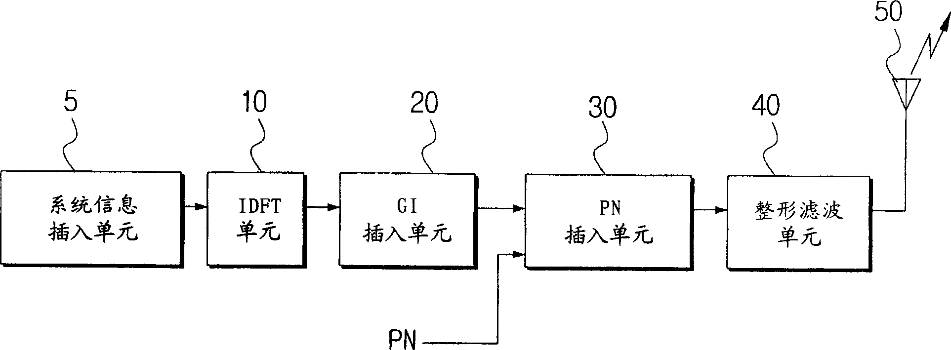
[0015] However, in the traditional multi-carrier transmission system, since the preamble and post-amble are inserted into the frame synchronization signal, the performance of the multi-carrier receiving system will be unsatisfactory when its range is short enough to consider ghosting
More specifically, since the conventional multi-carrier receiving system has to obtain additional information from the system information inserted in the frequency domain after signal processing or IDFT in the frequency domain at a predetermined time, the complete signal processing consumes a lot of time

Method used


Image

  • Multicarrier transmitting system for improving receiving efficiency of multicarrier receiving system and method thereof
  • Multicarrier transmitting system for improving receiving efficiency of multicarrier receiving system and method thereof
  • Multicarrier transmitting system for improving receiving efficiency of multicarrier receiving system and method thereof

Examples


Embodiment Construction

[0026] Preferred embodiments of the present invention will be described in more detail below with reference to the accompanying drawings.

[0027] image 3 is a schematic block diagram showing the multi-carrier transmission system of the present invention.

[0028] The multi-carrier transmission system of the present invention includes: a system information insertion unit 100, a system information generation unit 105, an inverse discrete Fourier transform (IDFT) unit 110, a guard interval (GI) insertion unit 120, a pseudo-noise (PN) sequence generation unit 130, Synchronization information forming unit 140 , synchronization information insertion unit 150 , shaping and filtering unit 160 , and antenna 170 . The synchronization information forming unit 140 includes an adding unit (not shown).

[0029] Figure 4 is to show image 3 A flowchart of a multi-carrier transmission method performed by the multi-carrier transmission system. The following will refer to image 3 and ...


PUM


Abstract

A system of transmitting a multi carrier for improving performance of a multi-carrier receiving system is provided to insert PN(Pseudo Noise) information for synchronizing a transmitter with a receiver into an OFDM signal, and to obtain synchronization in a previous time region before carrying out a DFT(Discrete Fourier Transform) function, thereby improving a signal processing speed. A GI(Guard Interval) inserter(120) inserts a GI into an OFDM signal to suppress an interference between symbols of the OFDM signal. A PN generator(130) generates PN information. A synchronous information former(140) adds system information to the PN information, and forms synchronous information. A synchronous information inserter(150) inserts the synchronous information in front of the GI. A system information inserter(100) inserts the system information into a transmission signal. An IDFT(Inverse DFT) portion(110) modulates the transmission signal to a time region, and forms the OFDM signal of the time region.

Description

technical field [0001] The present invention relates to a multi-carrier transmission system and a transmission method thereof, in particular to a multi-carrier transmission system and a transmission method capable of improving the signal processing speed of a multi-carrier reception system. Background technique [0002] Orthogonal Frequency Division Multiplexing, a multicarrier modulation scheme that provides good performance in environments such as multipath reception and mobile reception. [0003] OFDM uses multiple carriers in an orthogonal relationship to improve frequency utilization. Since it uses multiple carriers in wired / wireless channels, it is suitable for high-speed data transmission. Using a single carrier for high-speed data transmission with a short symbol period in a wireless communication channel with multipath fading will lead to serious inter-symbol interference. This increases the complexity of the receiving end. The OFDM scheme can use a tap (tap) sim...

Claims


Application Information

Patent Timeline
Patent Type & Authority Applications(China)
IPC IPC(8): H04N7/015H04J11/00H04L27/26
CPCH04L1/0042H04L27/2634H04N5/40H04L25/03019H04N21/2383H04N21/4382
Inventor 金正振
Owner SAMSUNG ELECTRONICS CO LTD
Learn More