
Array angular beam expander

An angular beam expander and beam expander technology, which is applied in the directions of instruments, optics, lenses, etc., can solve the problems of increasing system size and impossibly small focal length.

Inactive Publication Date: 2004-04-07
HUAZHONG UNIV OF SCI & TECH
View PDF0 Cites 18 Cited by
  • Summary
  • Abstract
  • Description
  • Claims
  • Application Information

AI Technical Summary

Problems solved by technology

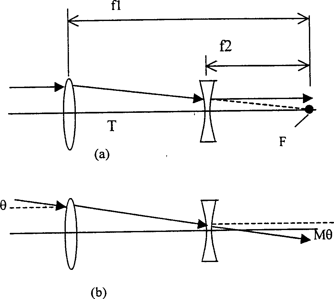
[0004] For existing angular beam expanders, in order to obtain a large angular magnification M, the focal length ratio of the front and rear lenses must be increased. However, for ordinary lenses, due to the limitation of the grinding process, the curvature radius of the lens surface is not It may be very small, generally greater than 5mm (or this order of magnitude), therefore, the focal length of the latter lens cannot be very small
On the other hand, when the beam aperture d required by the optical system is relatively large, to ensure light transmission, at least the curvature radius of the lens is required to be greater than half of the beam aperture. Further considering the aberration of the refractive surface, it is generally required that the curvature radius of the refractive surface is far larger Due to the beam aperture (for example, r2>10×d is usually required), so, for a large-aperture beam, the focal length f2 of the negative lens is quite large. At this time, the only way to increase the angular magnification M is to increase the focal length f1 of the previous lens. , and the distance between the positive and negative lenses (T=f1-f2) will inevitably increase, resulting in an increase in the size of the entire system

Method used


Image

  • Array angular beam expander
  • Array angular beam expander
  • Array angular beam expander

Examples


Embodiment Construction

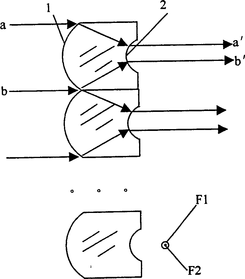
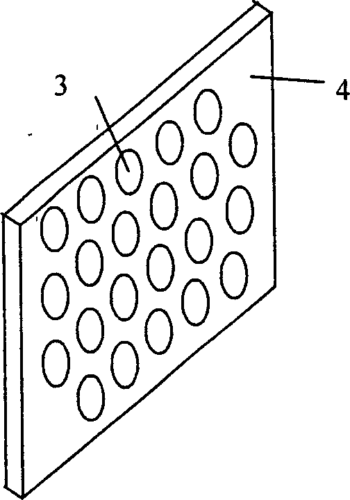
[0014] Such as figure 2 , image 3 As shown, the present invention combines a micro positive lens 1 with a micro negative lens 2 to form an angular beam expander assembly; then a large number of identical angular beam expander assemblies are arranged into a surface array ( figure 2 ), thus forming a new optical device. The particularity of the microlenses in this device is that the overall power of the microlens group composed of a single positive microlens and the corresponding negative microlens is zero. The advantage of this device is that it can have large angular magnification, large clear aperture and thin thickness at the same time.

[0015] This device has the following characteristics in terms of structure size:

[0016] 1) Each positive microlens has a corresponding negative microlens, and their optical axes coincide with each other (the optical axis refers to the normal of the center point of the surface of the microlens).

[0017] 2) The overall optical power...


PUM


Abstract

The array angular beam expander is a planar array comprising two or over identical angular beam expanding assemblies. Each of the assemblies consists of a positive micro lens and a negative micro lens, and the positive micro lens and the negative micro lens have such focal lengths and interval that the total focal power of the lens combination is equal zero. In the array, the intervals between the centers of any two adjacent micro lenses are equal. The thickness of the angular beam expander depends on the thickness between the positive micro lens and the corresponding negative micro lens. Each micro lens has very small sizes and this makes the said thickness limited even if the angular amplification is very great. Theoretically, increasing the number of micro lenses and the area of the array will makes it possible to hold all the incident light beams no matter how great the aperture of the incident beam is. The present invention has greatly reduced thickness compared with available angular beam expander.

Description

technical field [0001] The invention relates to an optical component, in particular to an array type angular beam expander. Background technique [0002] The function of the angular beam expander is to convert the incident plane light in one direction into the exiting plane light in another direction, and the angle between the incident light, the exiting light and the optical axis satisfies a fixed magnification. [0003] Usually, the angular beam expander is composed of two lenses or lens groups, one positive and one negative, which coincide with the focus (such as figure 1 shown), when a beam of plane light is incident on the positive lens on the left at an angle θ, it is focused on the focal plane of the positive lens, and the distance from the converging point to the optical axis is f1×θ, because the focus of the positive lens and The focal points of the negative lens are coincident, therefore, the converging light beam will still become a plane light after being refrac...

Claims


Application Information

Patent Timeline
Patent Type & Authority Applications(China)
IPC IPC(8): G02B3/08G02B27/09
Inventor 赵斌
Owner HUAZHONG UNIV OF SCI & TECH
Learn More