
Non-linear digital filtering method for handling binary noise

A technology of noise filtering and digital filtering, which is applied in digital technology networks, electrical components, impedance networks, etc., and can solve problems such as aging and environmental factors

Inactive Publication Date: 2004-03-31
HIGHER WAY ELECTRONICS
View PDF0 Cites 0 Cited by
  • Summary
  • Abstract
  • Description
  • Claims
  • Application Information

AI Technical Summary

Problems solved by technology

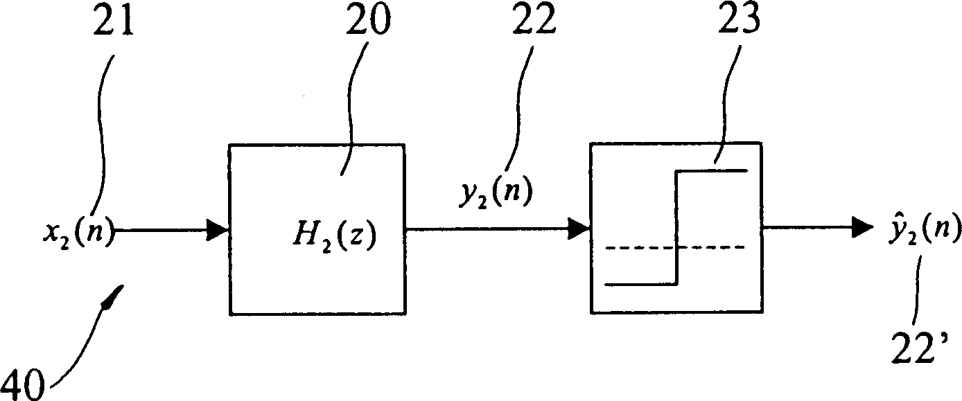
[0006] Another object of the present invention is to provide a kind of non-linear digital filter method that is used to process binary noise, it uses firmware (Firmware) to make non-linear digital filter, except can obtain better anti-noise effect, also It can save extra hardware cost and overcome the defect that noise filters that generally use analog circuits are susceptible to component aging and environmental factors

Method used


Image

  • Non-linear digital filtering method for handling binary noise
  • Non-linear digital filtering method for handling binary noise
  • Non-linear digital filtering method for handling binary noise

Examples


Embodiment Construction

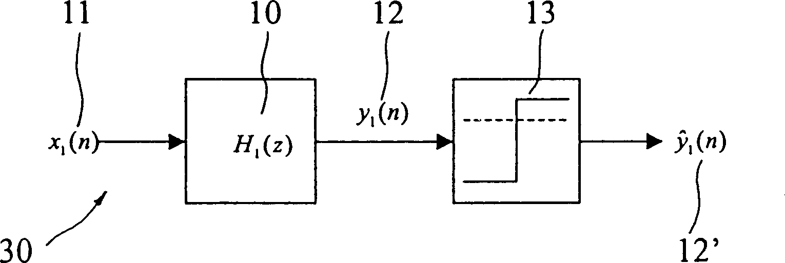
[0014] see first figure 2 As shown, it is a schematic diagram of the present invention for filtering low-level noise, which is mainly provided with a low-level noise filtering device 30, and the low-level noise filtering device 30 includes a digital filter H 1 (Z) 10 and a limiter 13, wherein the digital filter H 1 The input / output relationship of (Z)10 is as follows:

[0015] the y 1 (n) = 1 / 4x 1 (n)+1 / 2y 1 (n-1)+1 / 4y 1 (n-2);

[0016] where x 1 (n)11 is the input signal obtained by sampling, y 1 (n)12 is the output signal; in addition, in H 1 After (Z) 10, there is a limiter 13 whose levels are 0 and A, and the threshold value (Threshold) of the limiter 13 is set to αA, where 0.5<α<1.

[0017] An example is as follows: If the input signal x is disturbed by noise 1 When (n)11 is {0, 0, 0, 0, A, A, 0, 0, 0, 0}, it is assumed that the starting time is n=0, that is, x 1 (0)=0,x 1 (1)=0, and so on; where x 1 (4)=x 1 (5)=A is hypothetical low-level noise, under the ...


PUM


Abstract

The invention refers to a nonlinear digital filter method to process dual noise, especially adopting firmware to design a í«nonlinear digital filterí», producing filter effect on the noise of low-frequency radio-controlled timepieces, and having efficacies of overcoming the persecution of pulse-type dual noise, saving extra hardware cost, and preventing the parts from aging and being influenced by environmental factor.

Description

technical field [0001] The invention relates to a noise processing method of a low-frequency electric wave timing device, in particular to using a non-linear digital filter to process pulse-type binary noise that cannot be resisted by a general filter. Background technique [0002] Generally, low-frequency radio stations used to broadcast time are transmitted using a digital system, and the broadcast time information uses square waves with different duty cycles to represent binary "0" and "1". [0003] In addition, the system uses another square wave with a different duty cycle to represent the data frame identifier (Identifier Marker, M), which is used to define the position of the transmitted data. Using the Japanese system as an example, see figure 1 Shown is a signal element diagram, wherein the duty cycles of the signal elements representing "0", "1" and "M" are 80% "0", 50% "1" and 20% "M". [0004] But in fact, the demodulated signal at the receiving end is usually ...

Claims


Application Information

Patent Timeline
Patent Type & Authority Applications(China)
IPC IPC(8): H03H17/00
Inventor 何进安张清濠
Owner HIGHER WAY ELECTRONICS
Learn More