Teleconferencing system
A technology for video conferencing and conferencing, applied in video conferencing systems, two-way working systems, electrical components, etc., can solve problems such as MCU cannot be effectively used, and achieve easy setup and change, connection error prevention, and utilization optimization. Effect
- Summary
- Abstract
- Description
- Claims
- Application Information
AI Technical Summary
Problems solved by technology
Method used
Image

Examples
Embodiment approach 1
[0023] First, Embodiment 1 of the video conference system in the present invention will be described by referring to the drawings.
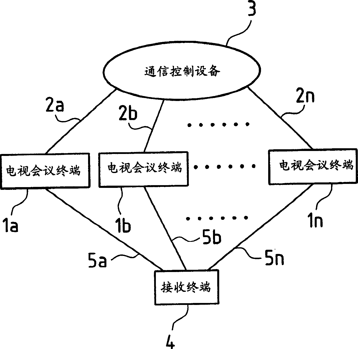
[0024] Fig.-1 is a block diagram illustrating an embodiment of a video conference system in the present invention.
[0025]In this embodiment, the video conference system includes: a plurality of video conference terminals 1a, 1b,...1n; multipoint communication in which lines 2a, 2b, ... 2n are connected; and a receiving terminal 4, which is connected to video conference terminals 1a, 1b, ... 1n via communication lines 5a, 5b, ... 5n and Accept a meeting request.
[0026] Each of the video conferencing terminals 1a, 1b, ... 1n is provided with information related to a first connection destination number (for example, a telephone number) for establishing a connection to the receiving terminal 4, and participates through the video conferencing terminal Conference participants in a videoconference are provided with an ID number and a password. Th...
Embodiment approach 2
[0041] Next, Embodiment 2 of the video conference system in the present invention will be described by referring to the drawings.
[0042] The difference between the video conference system in this embodiment and the above-described video conference system (Embodiment 1) is that the conference condition of the communication control device is set through the receiving terminal, and other aspects are the same as above.
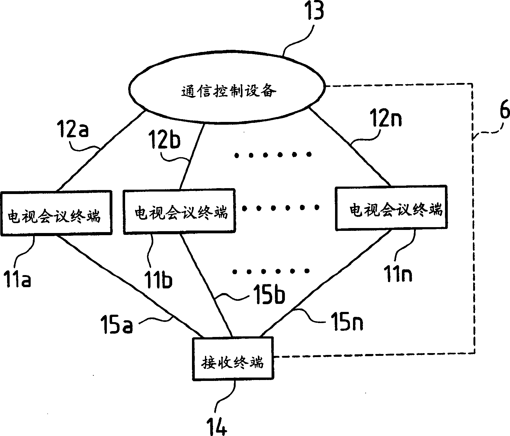
[0043] Fig.-3 is a block diagram illustrating another embodiment of the video conference system in the present invention. In this embodiment, the video conference system includes: a plurality of video conference terminals 11a, 11b, ... 11n; Multipoint communication in which communication lines 12a, 12b, ... 12n are connected; and a receiving terminal 14, which is connected to video conference terminals 11a, 11b, ... 11n via communication lines 15a, 15b, ... 15n And accept a meeting request and realize the setting of meeting conditions.
[0044] Each of the vid...
Embodiment approach 3
[0062] Next, Embodiment 3 of the video conference system in the present invention will be described by referring to the drawings.
[0063] The video conference system in this embodiment is characterized in that a conference condition of a communication control device is set and changed by using a video conference terminal when a conference is held.
[0064] The structure of this video conferencing system is the same as that of the video conferencing system shown in Fig.-1, and will not be described in detail in this embodiment.
[0065] In addition, the procedures related to the reservation of a meeting and the acceptance of a meeting request before the meeting can be the same as the conventional video conference system or the same as the video conference system in Embodiment 1 or 2.
[0066] When holding a conference, each of the video conference terminals 1a, 1b, ... 1n establishes a connection to the communication control device 3 via a communication line so as to hold a vi...
PUM
 Abstract
Description
Claims
Application Information
 - R&D
- Intellectual Property
- Life Sciences
- Materials
- Tech Scout
- Unparalleled Data Quality
- Higher Quality Content
- 60% Fewer Hallucinations
Browse by: Latest US Patents, China's latest patents, Technical Efficacy Thesaurus, Application Domain, Technology Topic, Popular Technical Reports.
© 2025 PatSnap. All rights reserved.Legal|Privacy policy|Modern Slavery Act Transparency Statement|Sitemap|About US| Contact US: help@patsnap.com