
3D projection system and method with digital micromirror device

A technology of projection system and optical system, applied in the field of video projection

Inactive Publication Date: 2004-03-03
REVEO
View PDF1 Cites 21 Cited by
  • Summary
  • Abstract
  • Description
  • Claims
  • Application Information

AI Technical Summary

Problems solved by technology

[0026] The fundamental problem with stereoscopic imaging is that the two perspective images should be displayed in such a way that they appear simultaneously to a viewer, with each eye seeing only the corresponding perspective image

Method used


Image

  • 3D projection system and method with digital micromirror device
  • 3D projection system and method with digital micromirror device
  • 3D projection system and method with digital micromirror device

Examples


Embodiment Construction

[0078] Figure 6 is a representative system block diagram 600 of the present invention. The block diagram shows both the data flow and the optical image flow of the system. This stream of optical images is denoted by the term "rays", and it flows in a vertical direction except for the lower part of the stream. Data flow is represented as a horizontal channel starting from the left of the graph and going to the right. Starting from the upper left region of the illustration, the block diagram shows four separate inputs; two for RGB (computer) 602 and 604 and two for video 606 and 608 . Other input types are also possible. For these video inputs, any or all of the three video formats Composite, S-Video, or Component can be implemented. To accommodate the widest range of possible inputs, the desired embodiment provides a total of 8 separate inputs including left and right RGB, left and right composite video, left and right S-video, and left and right component video.

[0079]...


PUM


Abstract

This application is related to video projection using digital light processing techniques and in particular to stereoscopic video projection. A digital micro-mirror device based 3D projection system has a 3D data system coupling 3D images to an electrical input of a color system and digital micro-mirror display device and a 3D optical system coupling an output of a light source through an optical path comprising said digital micro-mirror display device, a 3D optical encoder and projector optics to a display medium; wherein said 3D projection system displays 3D images onto said display medium. The data system includes at least two front end processing portions, a 3D data formatter, a digital micro-mirror device data formatter and a digital micro-mirror display device. Such 3D data system provides color system control signals to a color system and 3D encoder as well as digital micro-mirror display data to said digital micro-mirror display device. A method of converting a digital micro-mirror device based 2D projection system to a digital micro-mirror device based 3D projection system includes installing a 3D data formatter; installing a digital micro mirror device data formatter; optionally replacing an existing color wheel with a color wheel formatted for 3D; and installing 3D optical encoder system in one of three positions in an optical path of said system.

Description

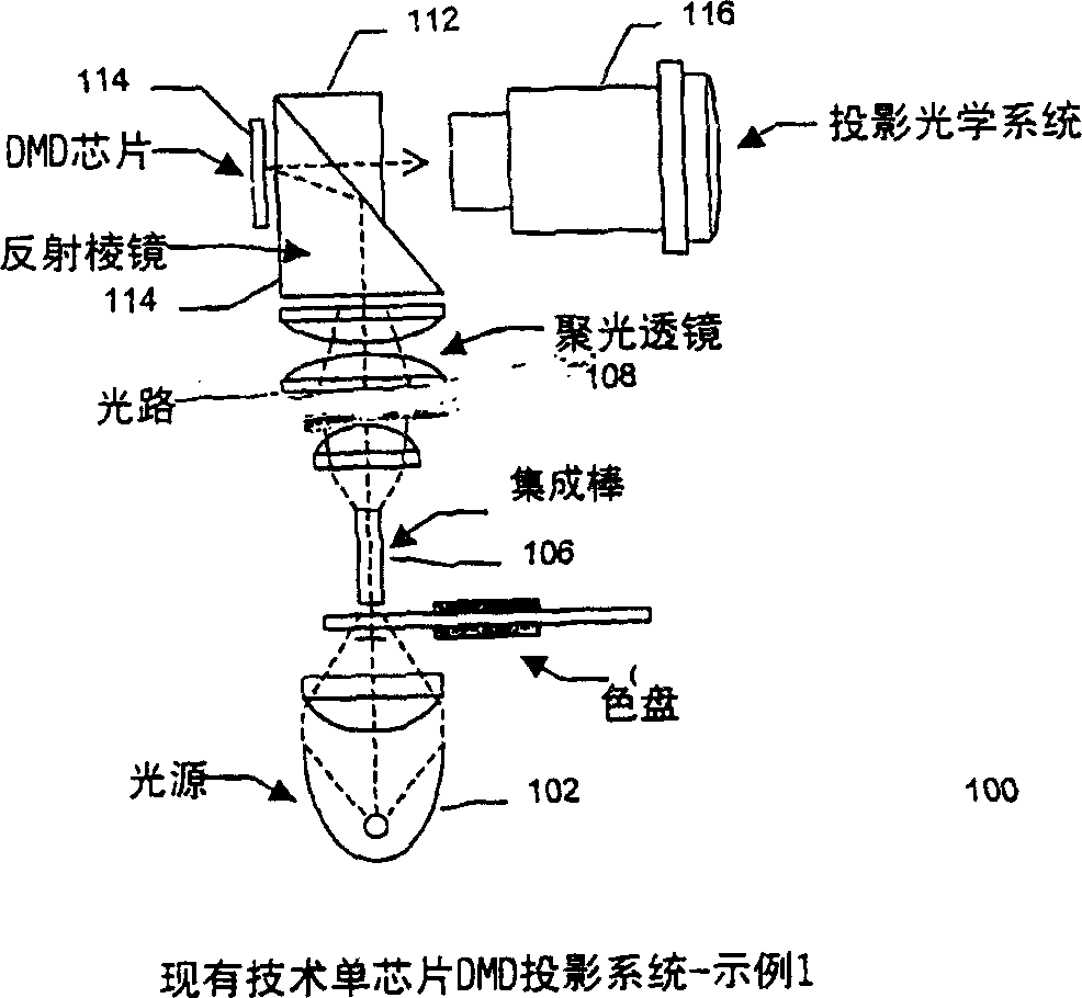
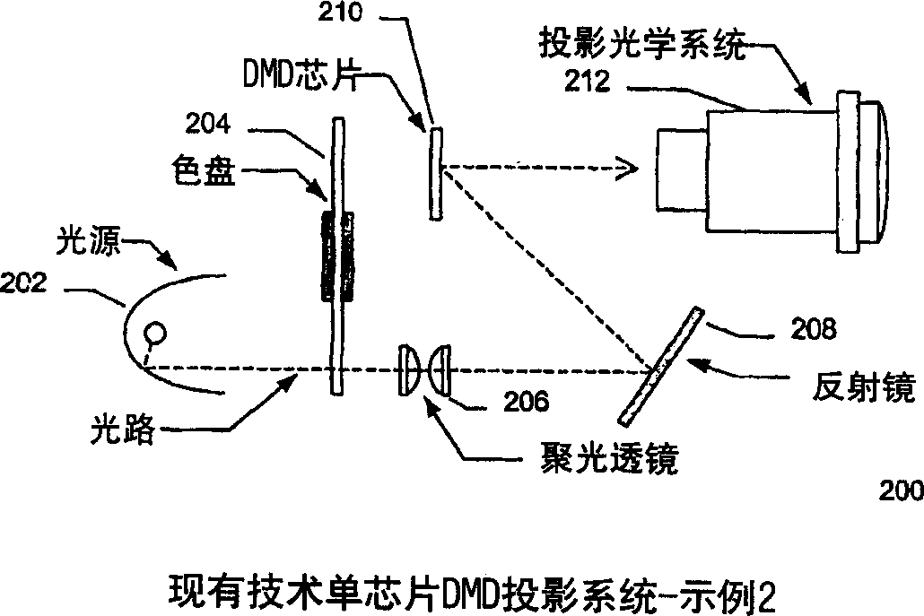
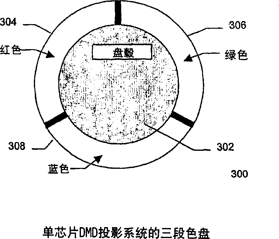
[0001] related application [0002] This application is related to a provisional application serial number 60 / 239,664, filed on October 12, 2000, entitled "DLP Based 3D Projection System" and filed on January 12, 2001, entitled " Another provisional application serial number 60 / 261,136 for Method and apparatus for stereoscopic display using digital light processing (method and apparatus for stereoscopic display using digital light processing)". Both references are hereby incorporated by reference. field of invention [0003] This application relates to video projection using digital light processing technology, in particular to stereoscopic video projection. Background of the invention [0004] Texas Instruments' Digital Light Processing (DLP) technology has proven to be a viable and reliable technology for data and multimedia image projection systems. The basis of DLP technology is the Digital Micromirror Device (DMD), also from Texas Instruments, which is described in ma...

Claims


Application Information

Patent Timeline
Patent Type & Authority Applications(China)
IPC IPC(8): G02B26/00G02B7/00G02B27/18G02B27/22G02B30/25G09G3/00G09G3/20G09G3/34H04N5/74H04N9/31H04N13/239
CPCH04N13/0454H04N19/00769H04N2005/7466G09G3/346H04N13/0459H04N13/0438H04N13/0239G09G3/002G09G3/003H04N13/0497H04N5/7458H04N13/0285G02B27/2207G03B33/08G09G2320/0247H04N13/0055G02B27/2264H04N13/0059G02B27/26H04N13/0456H04N13/0431H04N9/3197G03B35/16H04N13/0427H04N9/3114H04N13/0003H04N13/0434H04N9/3188G09G2310/0235G02B26/008H04N19/597H04N13/0037H04N13/0422H04N13/337H04N13/341H04N13/194H04N13/189H04N13/324H04N13/334H04N13/363H04N13/10H04N13/286H04N13/15H04N13/365H04N13/359H04N13/239H04N13/361H04N13/398G02B30/23G02B30/24G02B30/25
Inventor 亚当·W·迪韦尔比斯戴维·C·斯威夫特
Owner REVEO
Learn More