
Electronic component mounting board, method of manufacturing the same, electronic component module, and communications equipment

一种电子元件安装、电子元件的技术,应用在电气元件、印刷电路制造、印刷元件电连接形成等方向,能够解决效率低、热量排放的效率低等问题

Inactive Publication Date: 2004-01-14
PANASONIC CORP
View PDF1 Cites 4 Cited by
  • Summary
  • Abstract
  • Description
  • Claims
  • Application Information

AI Technical Summary

Problems solved by technology

Thus, when the diameter of the via is too small, it results in lower efficiency during fabrication due to the cracking of the expanded metal on the via.
[0012] At the same time, when the diameter of the through hole is too small, a gap appears between the metal corrugation and the through hole after drying, so that the efficiency of heat discharge is low

Method used

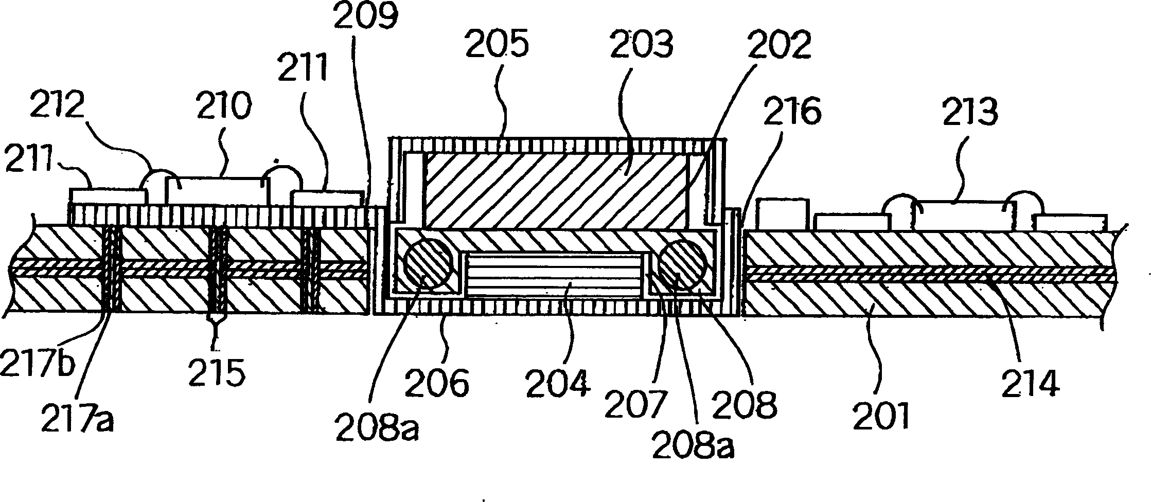
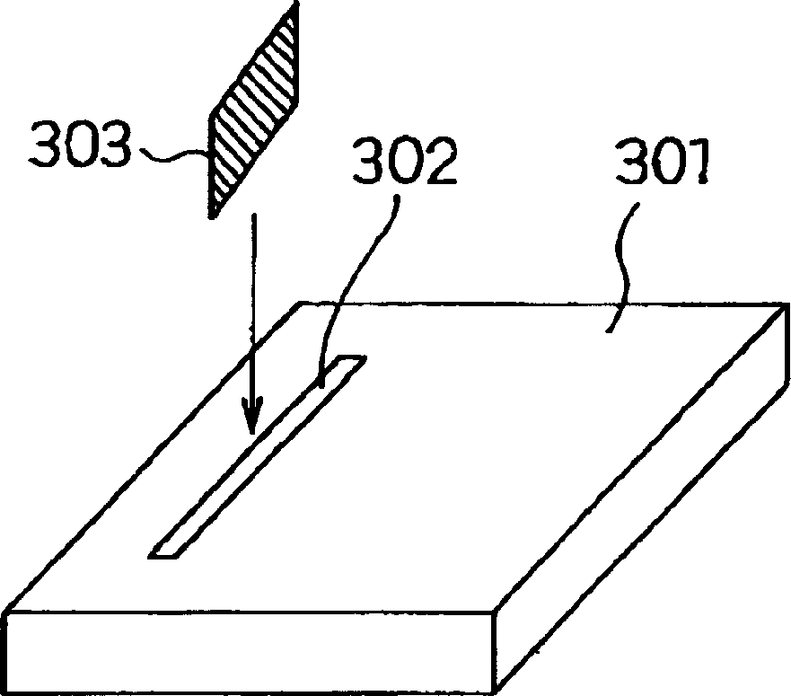

Image

  • Electronic component mounting board, method of manufacturing the same, electronic component module, and communications equipment
  • Electronic component mounting board, method of manufacturing the same, electronic component module, and communications equipment
  • Electronic component mounting board, method of manufacturing the same, electronic component module, and communications equipment

Examples


Embodiment Construction

[0070] An electronic component mounting board according to an embodiment of the present invention and a transmission module for radio communication equipment using the mounting board will be discussed below with reference to the accompanying drawings.

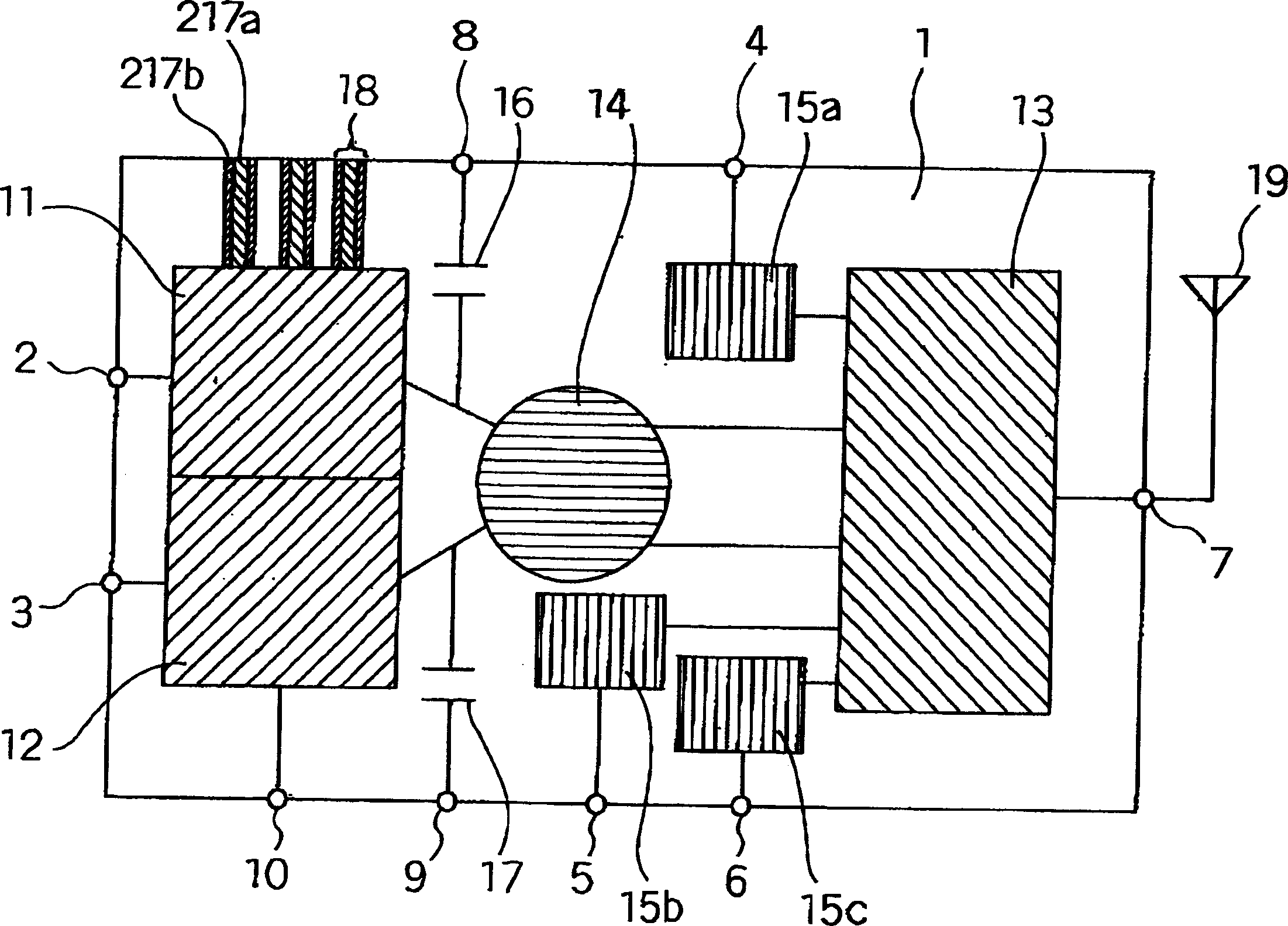
[0071] figure 1 A concept showing the block diagram structure of the transmission module of the radio communication device of this embodiment of the present invention. Although an example of a portable telephone for EDGE of GSM / DCM / PCS will be described below, the application of the present invention is not limited to this example.

[0072] figure 1 The label 1 in the table represents a ceramic plate as an example of the electronic component mounting board of the present invention, wherein the label 2 represents the GSM transmission input terminal, the label 3 represents the DCS / PCS transmission input terminal, the label 4 represents the GSM receiving output terminal, and the label 5 represents the DCS receiving terminal. O...


PUM

PropertyMeasurementUnit
relative permittivityaaaaaaaaaa

Abstract

A ceramic laminated board is provided which has thermal via holes penetrating the inside from the main face of the board. In the thermal via hole, a heat transfer body is placed which has a metallic body and a composite material provided entirely or partially between the metallic body and the ceramic laminated board. The composite material is higher in thermal conductivity than air and is lower in thermal expansion coefficient than the metallic body.

Description

technical field [0001] The present invention mainly relates to a high-frequency portion electronic component mounting board for radio communication equipment such as a transmission module of radio communication equipment, and an electronic component module using such a mounting board. Background technique [0002] In recent years, a series of antenna switch duplexer modules and power amplifier modules have been used in the high frequency section of radio communication equipment. An example of a conventional single module and a high frequency part of a radio communication device formed by combining a plurality of modules will now be discussed with reference to the accompanying drawings. [0003] Figure 5 is a block diagram showing the use of an antenna switch duplexer module and a power amplifier module in general radio communication equipment. Figure 5 The reference numeral 406 in the diagram represents an antenna switch duplexer module, the reference numeral 404 represent...

Claims


Application Information

Patent Timeline
Patent Type & Authority Applications(China)
IPC IPC(8): H01L23/367H01L23/66H05K1/02H05K1/03H05K3/40
CPCH05K2201/086H01L2924/3011H01L24/48H01L2924/01079H01L2924/09701H01L2224/16H01L2224/48227H01L2924/0102H01L23/66H05K2201/09063H05K1/0204H01L2924/01078H05K1/0243H05K1/0306H05K2201/10416H01L23/3677H01L2924/19041H01L2924/01012H01L2224/16225H01L2224/48091H01L2924/01087H05K3/4046H01L2224/05599H01L2224/85439H01L2224/85444H01L2224/45099H01L2224/85399H01L2924/14H01L2924/00014H01L2924/00
Inventor 石崎俊雄
Owner PANASONIC CORP
Learn More