
Telephone set with on hold function

A telephone and telephone technology, applied in the field of telephones, can solve problems such as lack of free hands, delay in answering incoming calls, and inability to answer calls immediately

Inactive Publication Date: 2003-12-17
KONINKLIJKE PHILIPS ELECTRONICS NV
View PDF3 Cites 1 Cited by
  • Summary
  • Abstract
  • Description
  • Claims
  • Application Information

AI Technical Summary

Problems solved by technology

What is not mentioned is that when the user is not on a call, he or she has to postpone answering an incoming call
Normally, it is expected that a user who is not on a call can answer the call or let the phone ring when an incoming call comes in, but we have found that there are cases where the user is so engrossed in the call that he cannot answer the call right away, or he or Her hands were too empty to answer the phone right away

Method used


Image

  • Telephone set with on hold function
  • Telephone set with on hold function
  • Telephone set with on hold function

Examples


Embodiment Construction

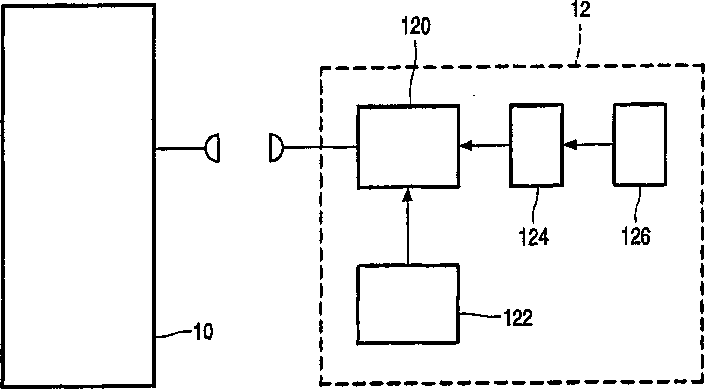
[0014] figure 1 Indicates a part of a telephone device. The arrangement comprises a base station 10 and a telephone 12 (without departing from the invention, a switch permanently connected to the telephone 12 could be used). The telephone 12 includes a control unit 120 , a ringing unit 122 , a voice input unit 126 and a voice recognition unit 124 .

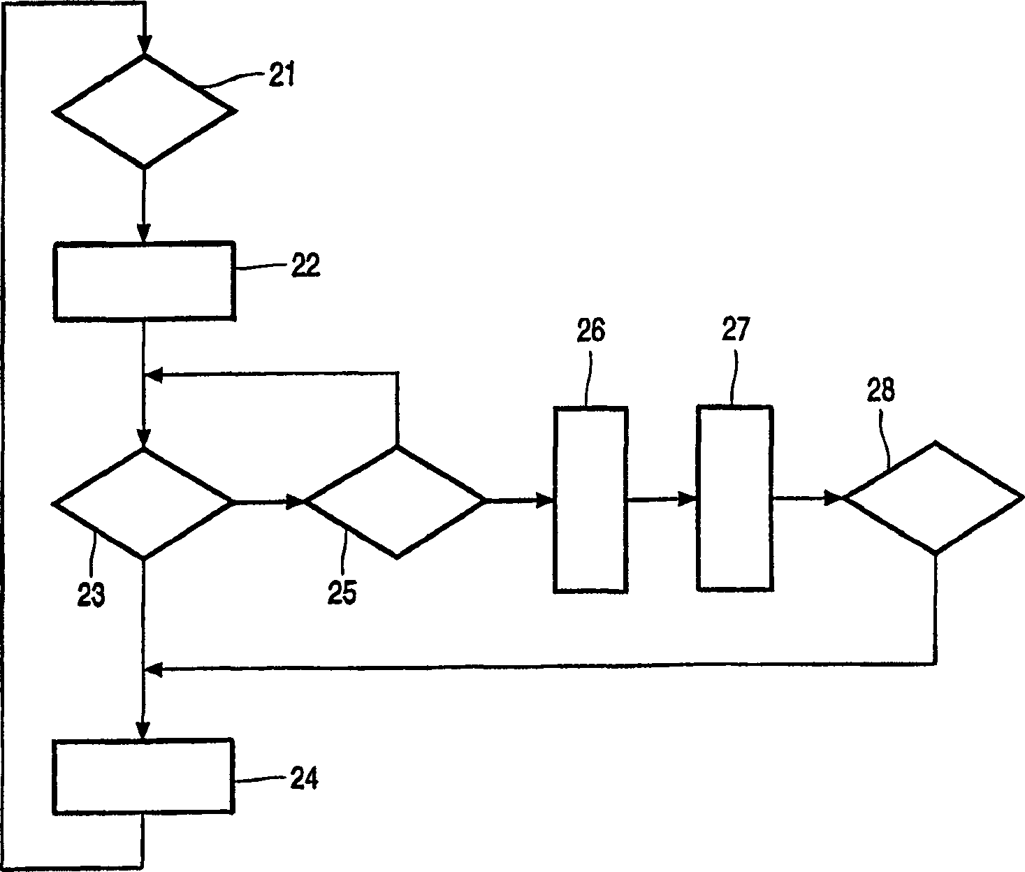
[0015] figure 2 A flowchart showing the processing of an incoming call.

[0016] In operation, the control unit 120 monitors whether setting information of an incoming call is received in the first step 21 of the flowchart. This monitoring continues until such setting information has been received. If it is received, the control unit 120 executes the second step 22, which makes the ringing unit start to send a signal to the user to indicate that an incoming call is received, for example, by ringing or vibrating (for simplicity, hereinafter all referred to as ringing). Signal (here, the person holding the telephone 12 is gene...


PUM


Abstract

A telephone set starts ringing when receiving in incoming call. The user of the telephone set is able to give an on-hold user command given after start of said signaling. In response to the on-hold command the incoming call is placed automatically on-hold.

Description

field of invention [0001] The invention relates to a telephone set with a call hold function. Background technique [0002] Various techniques are known for answering a phone call when the user has indicated that he or she is unable or unwilling to answer the call. Automatic answering of incoming calls in such situations is known, for example, from US patent 6,055,305. Similarly, an automatic reply may be provided when an incoming call is not answered within a predetermined time interval. [0003] All of these techniques assume that the user will not be available for an indeterminate amount of time. The purpose of automatically handling incoming calls is then to end the phone call. [0004] Conversely, when the line is busy when an incoming call arrives, it can be assumed that the user will be available for the foreseeable future. Japanese Patent Application 2-142263 discloses how to put the incoming call on "hold" during the previous call. The called user notices the i...

Claims


Application Information

Patent Timeline
Patent Type & Authority Applications(China)
IPC IPC(8): H04M1/72513H04M1/80H04M1/00H04M1/64
CPCH04M1/72513H04M1/00
Inventor C·車Y·-C·楚
Owner KONINKLIJKE PHILIPS ELECTRONICS NV
Learn More