
Rope transmission mechanism

A technology of rope transmission and rope pulley, which is applied in the direction of transmission devices, mechanical equipment, belts/chains/gears, etc., can solve the problems of unsuitable transmission of super high power, high cost of gear transmission, inaccurate transmission ratio, etc., so as to save the need for deceleration The effect of low material requirements for the machine and wheel body and simple structure of the sheave

Inactive Publication Date: 2003-12-17
徐际长
View PDF0 Cites 10 Cited by
  • Summary
  • Abstract
  • Description
  • Claims
  • Application Information

AI Technical Summary

Problems solved by technology

Although these two types of transmission have made outstanding contributions in the machine manufacturing industry, they still have their own shortcomings: gear transmission costs are high, lubrication requirements are high, noise is large, and it is not suitable for transmitting super-high power, or the cost is extremely high when transmitting super-high power
The transmission ratio of the belt drive is inaccurate, and it is not suitable for environments with high temperature and corrosive media
belt life is short
Chain transmission requires high lubrication, high noise, and high cost of the chain

Method used


Image

  • Rope transmission mechanism
  • Rope transmission mechanism
  • Rope transmission mechanism

Examples


Embodiment Construction

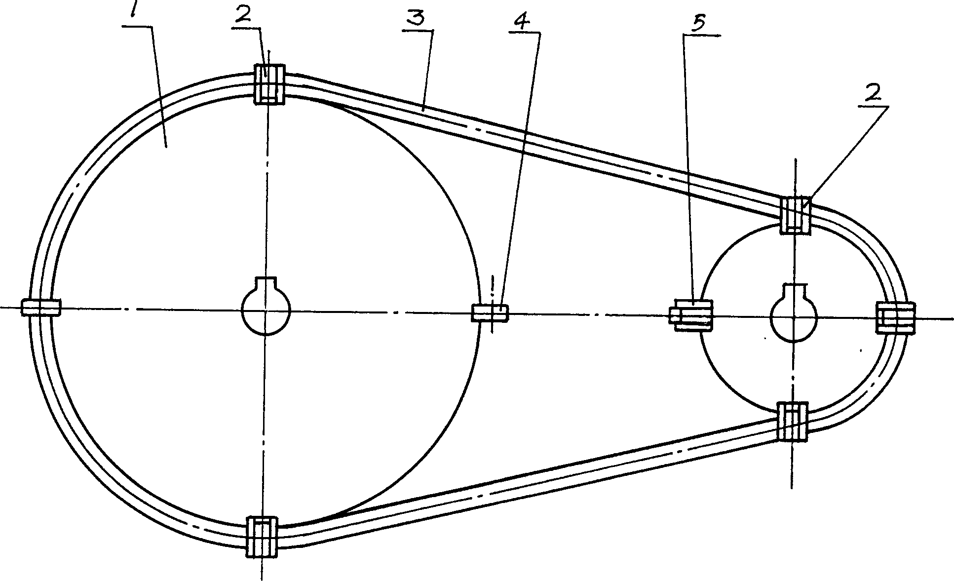
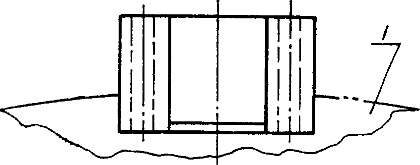
[0035] refer to Figure 1 to Figure 19 , the outer edge of the rope wheel 1 does not have the buckle 2 and the flat plate tripping 4 that are fixed with the wheel 1, and the rope 3 that forms the loop is tightly placed on the two wheels 1. Buckle 5 is the buckle when the rope is not buckled (compared to Image 6 or Figure 15 ), buckle 2 is fixedly installed by fastening bolt 7 and wheel 1. The buckle bolt 9 is looped on the buckle shaft 6, and is inserted into the buckle frame 8 alive. Rope 3 is fastened by fastening point 11 ( Figure 4 There are two fastening points 11 on it, so it is called multi-point buckle; Figure 12 There is a fastening point 11 on it, so it is called a single-point buckle), a rope-passing notch 12 is formed between the buckle bolt 9 and the buckle frame 8, and there are corresponding rope-passing notches on the flat trip 4 and the multi-pile trip 14 12. Flat studs are mainly suitable for passing knotted ropes, and multi-pile trips 14 are mainly...


PUM


Abstract

A rope driving mechanism is composed of two rope wheels and an endless rope. Said rope has nodes on it. Said rope wheel has the stambling blocks for driving the rope. Its advantages are high drive efficiency for ultrahigh-power drive, simple structure and very low cost.

Description

Technical field [0001] The invention relates to a mechanical transmission mechanism, especially a rope transmission mechanism formed by combining a sheave and a rope. Background technique [0002] The most commonly used transmission mechanism known at present has the disturbance transmission and the gear transmission that comprise belt transmission and chain transmission. Although these two types of transmission have made outstanding contributions in the machine manufacturing industry, they still have their own shortcomings: gear transmission costs are high, lubrication requirements are high, and noise is large. They are not suitable for transmitting super-high power, or the cost is extremely high when transmitting super-high power. The transmission ratio of the belt drive is not accurate, and it is not suitable for environments with high temperature and corrosive media. The life of the belt is short. Chain transmission requires high lubrication, high noise and high chain ...

Claims


Application Information

Patent Timeline
Patent Type & Authority Applications(China)
IPC IPC(8): F16H7/04
Inventor 徐际长
Owner 徐际长
Learn More