
Switch resistance drive device control

A switched reluctance motor and magnetic technology, applied in the direction of electromechanical devices, magnetic circuit rotating parts, magnetic circuit shape/style/structure, etc., can solve the problems of limiting motors, increasing winding loss, multi-space, etc., and achieve low loss Effect

Inactive Publication Date: 2003-11-12
先进电机有限公司
View PDF2 Cites 11 Cited by
  • Summary
  • Abstract
  • Description
  • Claims
  • Application Information

AI Technical Summary

Problems solved by technology

However, prior art motors of this type have the disadvantage that the windings extending over more than one stator pole have to be connected with long end connections, which increases the overall winding losses and makes the motor take up more power. space, which limits the range of motors that can be manufactured with low cost

Method used


Image

  • Switch resistance drive device control
  • Switch resistance drive device control
  • Switch resistance drive device control

Examples


Embodiment Construction

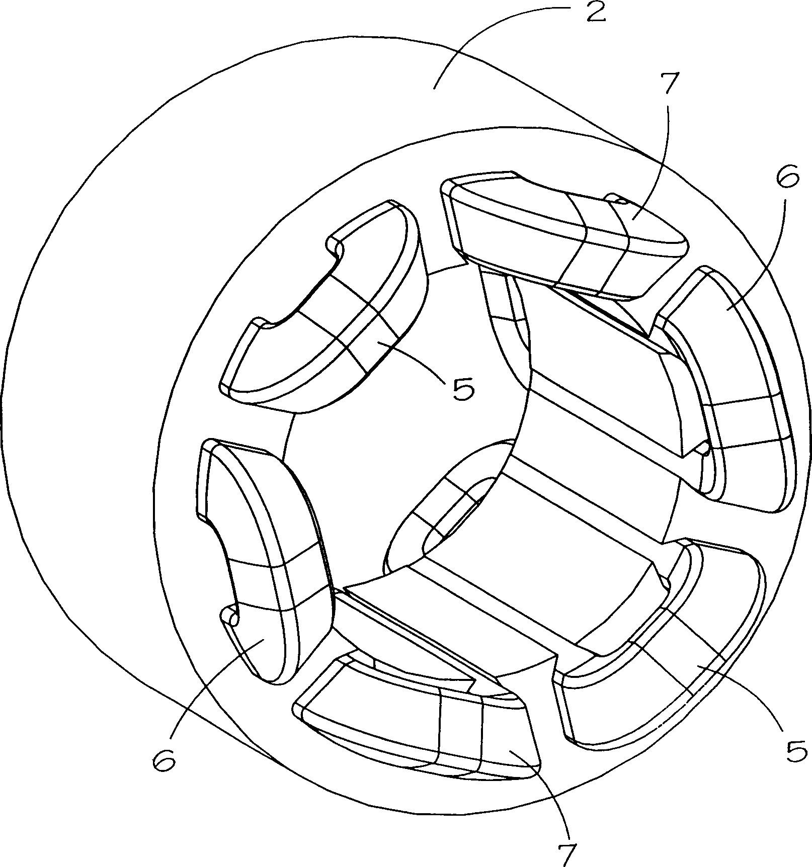
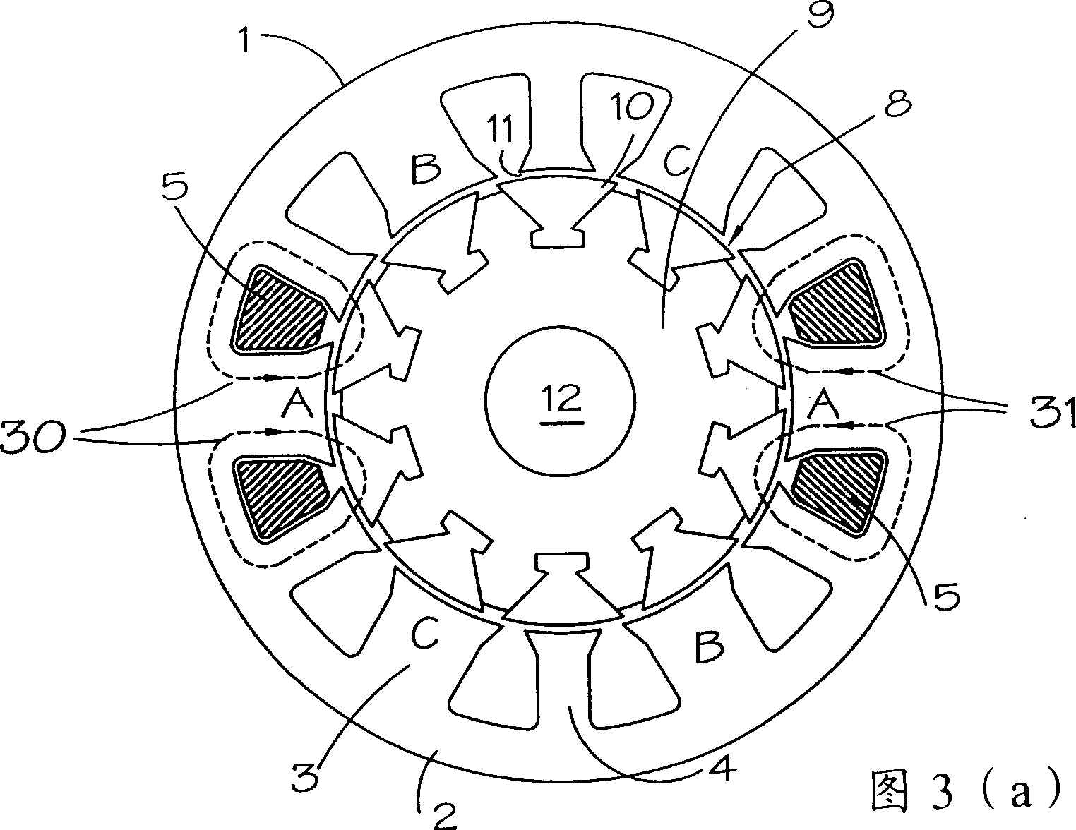
[0023] see figure 1 and 2 , a three-phase switched reluctance motor 1 comprises a stator 2 having a plurality of wider first stator poles 3 and narrower second stator poles 4 arranged alternately. In the illustrated embodiment, the stator 2 has six first stator poles 3 and six second stator poles 4 . Each first stator pole 3 is wound with a corresponding excitation coil 5, 6, 7 for the three phases. The coils are mounted in diametrically opposed coil pairs such that the diametrically opposed coil pairs are electrically connected to each other in series. In an alternative embodiment, completely diametrically opposed coils are connected in parallel.

[0024] The rotor 8 includes a magnetless core 9 . Ten magnetically separated rotor segments 10 of magnetic material are clamped in longitudinal keyways in core 9 so that they are circumferentially aligned and separated from stator poles 3 , 4 by air gaps 11 . The rotor segment 10 is arranged to direct the magnetic flux from a ...


PUM


Abstract

A switched reluctance machine has a stator which has an array of alternate wide and narrow poles around its inner circumference. Coils are wound around the wide poles only. The rotor comprises segments of soft magnetic material carried on a non-magnetic core. The segments are so proportioned at the airgap that the flux produced by one stator coil passes through two or more segments and returns through the adjacent narrow poles. The machine is capable of producing a high output.

Description

technical field [0001] This invention relates to switched reluctance machines, and more particularly to switched reluctance machines having segmented rotors. Background technique [0002] As is well known, the stator of a switched reluctance motor has a series of stator poles of soft magnetic material arranged on a circumference, said stator having a current-carrying coil wound around each pole. A rotor having rotor poles of magnetic material is rotatably mounted relative to the stator and seeks to align itself with a magnetic field generated by energized one or more coils. The coils of the stator poles are excited in order to generate a desired torque on the rotor relative to the stator. [0003] The amount of torque produced by such a motor depends on the number of turns of the excitation coil connected under alignment (i.e., rotor and stator pole alignment) and non-alignment (i.e., maximum misalignment of rotor and stator poles) conditions. The difference between the ma...

Claims


Application Information

Patent Timeline
Patent Type & Authority Applications(China)
IPC IPC(8): H02K19/10
CPCH02K19/103H02K19/06
Inventor B·C·梅克劳
Owner 先进电机有限公司
Learn More