Landing gear apparatus and assembling method thereof

A landing gear and input shaft technology is applied in the field of a landing gear device supporting a semi-trailer, and a method for assembling a landing gear device bracket

Inactive Publication Date: 2003-11-05
SAF霍兰德公司
View PDF1 Cites 7 Cited by
  • Summary
  • Abstract
  • Description
  • Claims
  • Application Information

AI Technical Summary

Problems solved by technology

In addition to the above-mentioned landing gear bracket, the above-mentioned conventional structure also requires a certain number of parts and multiple manufacturing steps to assemble the gear transmission in the above-mentioned gearbox with the above-mentioned bracket, input and output shafts

Method used


Image

  • Landing gear apparatus and assembling method thereof
  • Landing gear apparatus and assembling method thereof
  • Landing gear apparatus and assembling method thereof

Examples


Embodiment Construction

[0043] Detailed description of the preferred embodiment

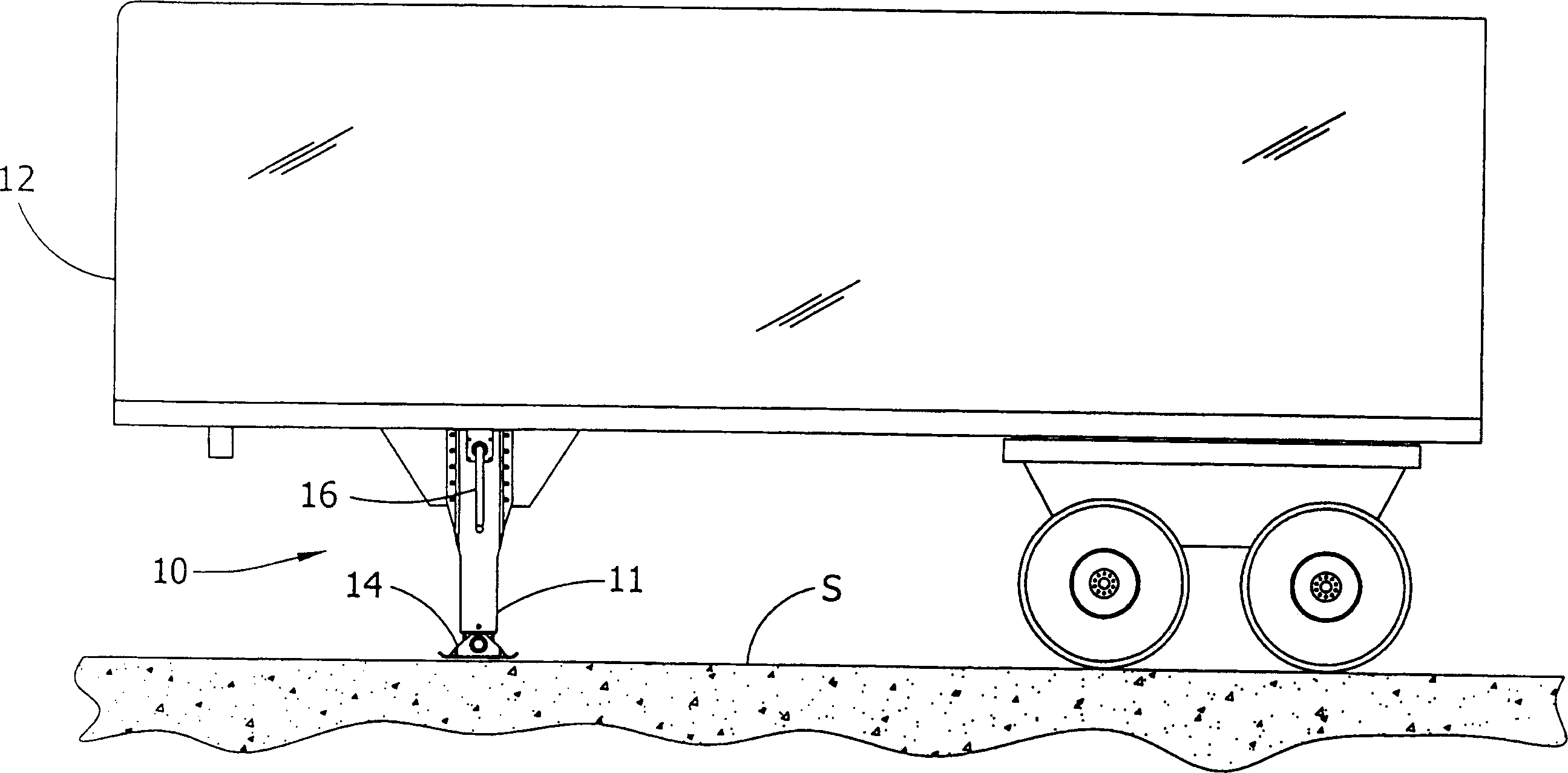
[0044] figure 1 Illustrates the undercarriage, generally indicated at 10, for supporting the semi-trailer when the semi-trailer is not coupled to a tractor. The landing gear arrangement 10 generally includes a pair of brackets 11 (only one bracket is shown) respectively located at the front corners of the semi-trailer 12 . As is well known, each bracket 11 can be extended to engage the road surface S or other supporting surface, thereby holding the front of said semi-trailer. The foot 14 of the undercarriage 10 is pivotally mounted on the bracket 11 and engages with the road surface S. As shown in FIG. When the above-mentioned semi-trailer 12 is dragged on the ground by a tractor (not shown), the bracket 11 can also be retracted to leave the ground. The crank handle 16 is generally used to extend and contract the length of the above-mentioned bracket 11, as will be described below. The following description is limit...


PUM


Abstract

Landing gear (10) for selectively supporting a semitrailer (12) and a method of assembly of the landing gear is provided. The landing gear (10) includes a leg (11) having an upper section (15) and a lower section (13) telescopingly received in the upper section (15). A lead screw (23) extends and retracts the upper and lower sections relative to each other upon rotation thereof. An input shaft (27) applies a torque to the lead screw (23) to drive rotation thereof, the input shaft (27) being rotatable about a rotation axis and movable in translation along the rotation axis for shifting between a first position for a low gear operation and a second position for a high gear operation. An output shaft (31), axially aligned with the input shaft (27), has an output gear (35) for transmitting torque to the lead screw (23). A gearing subassembly (32) is received in the upper leg section (15) and is configured to augment lift when the input shaft (27) is in the first position and augment speed in the second position.

Description

Background of the invention [0001] The present invention generally relates to a landing gear arrangement for supporting a semi-trailer, and more particularly to a gear transmission structure of the landing gear arrangement. [0002] The undercarriage of the invention finds particular application in the support of semi-trailers when the semi-trailer and tractor are not connected. Conventional undercarriages include a pair of telescoping legs that extend into engagement with the road or other supporting surface to hold the front end of the semi-trailer, retract and clear the ground when the semi-trailer is towed along the road by a tractor. The above-mentioned extension and retraction are often accomplished by the operator manually turning a crank connected to the lead screw of the above-mentioned telescopic bracket through a gear device. The lead screw is connected to the telescopic frame portion of the frame so that a lower frame portion can be retracted into an upper frame p...

Claims


Application Information

Patent Timeline
IPC IPC(8): B62D53/06B60S9/08
CPCB60S9/08
Inventor M·W·彭维勒
Owner SAF霍兰德公司
Why Eureka
Try Eureka