
Sustrate olelivery mechanism

A technology of conveying mechanism and substrate, which is applied to conveyor objects, pile separation, lighting and heating equipment, etc., can solve the problems of insufficient curing, complicated curing work, and the curing of both sides of the substrate cannot be carried out at the same time.

Inactive Publication Date: 2003-10-22
ORC MFG
View PDF1 Cites 17 Cited by
  • Summary
  • Abstract
  • Description
  • Claims
  • Application Information

AI Technical Summary

Problems solved by technology

As a result, uneven radiation occurs on the underside of the substrate, resulting in insufficient and uneven curing
As a result, the substrate needs to be turned over for curing, which complicates curing
Therefore, in the case of using the gas suspension mechanism, the curing of both sides of the substrate cannot be performed simultaneously.

Method used


Image

  • Sustrate olelivery mechanism
  • Sustrate olelivery mechanism
  • Sustrate olelivery mechanism

Examples


Embodiment Construction

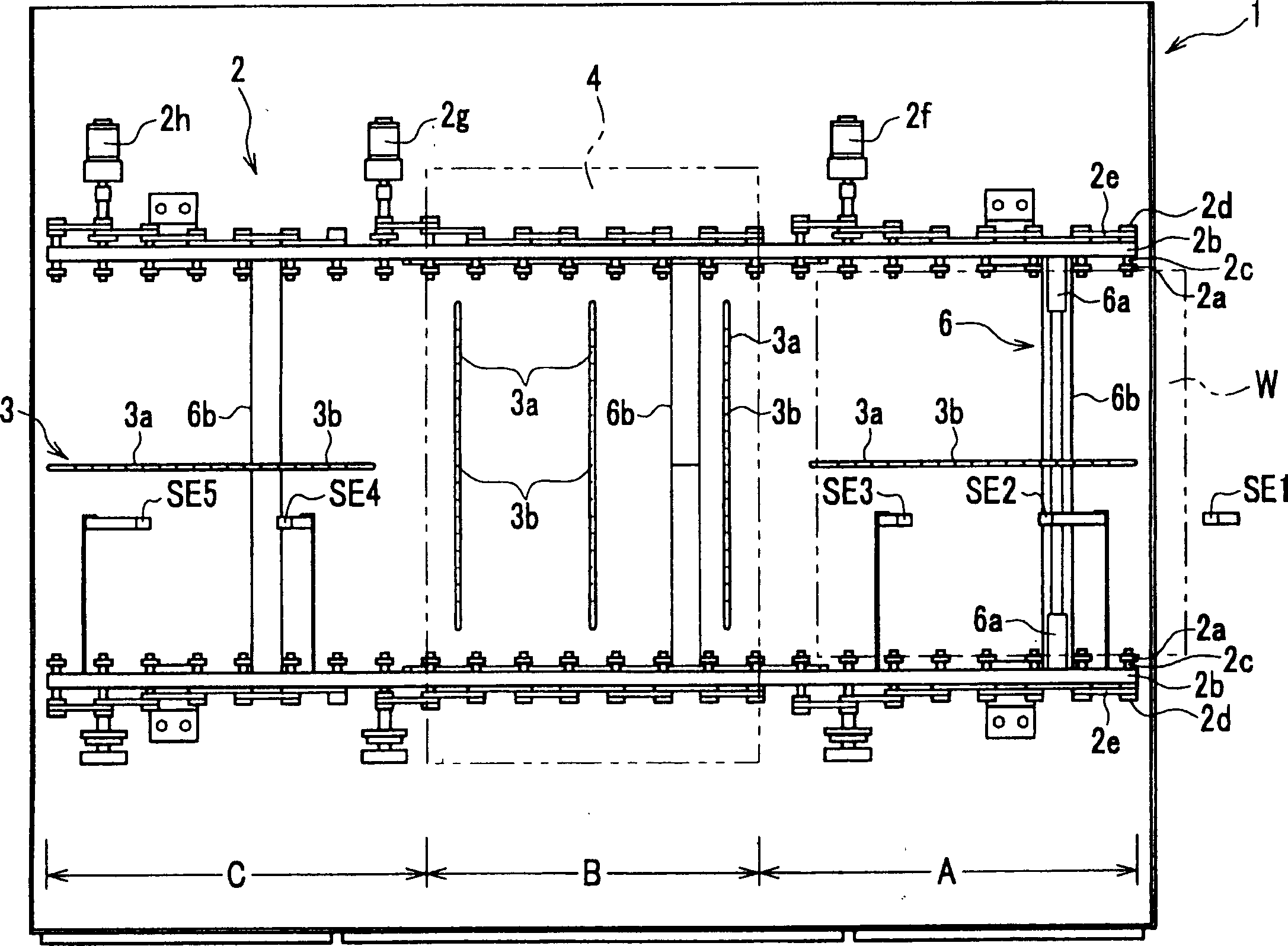
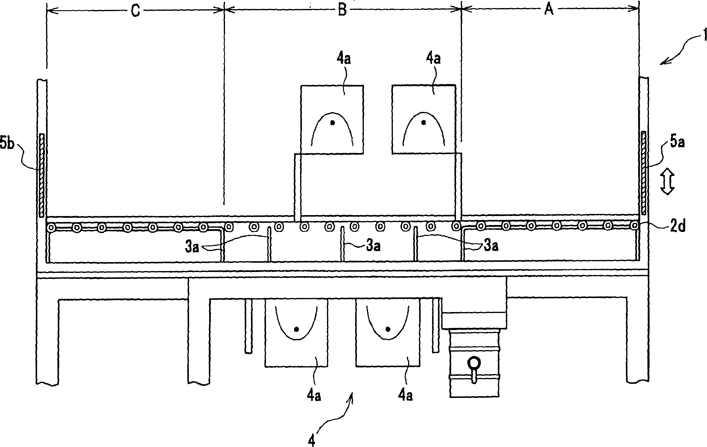
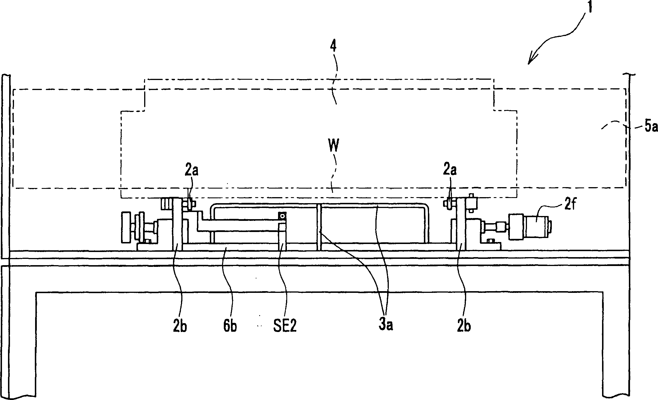
[0043] Embodiments of the present invention will be described below with reference to the accompanying drawings. figure 1 is a plan view showing the main part of an ultraviolet radiation apparatus utilizing a substrate transport mechanism. figure 2 yes figure 1 front view. image 3 yes figure 1 A side view of . Figure 4 A is a schematic perspective view of the substrate transfer auxiliary mechanism. Figure 4 B is a partial end view taken along line A-A.

[0044] Such as figure 1 As shown, the substrate conveying mechanism 2 is equipped with: some conveying rollers 2a, which are used to support the two ends of the substrate W to convey the substrate W; The lower portion of the substrate W supports the substrate W in a non-contact state.

[0045] In addition, the substrate transfer mechanism 2 is divided into three parts: a stand-by part A at which ultraviolet rays are not emitted; a send-out part C; and a radiation part B at which ultraviolet rays are emitted . The ...


PUM

PropertyMeasurementUnit
thicknessaaaaaaaaaa
weightaaaaaaaaaa

Abstract

The present invention provided a base transporting mechanism capable of stably transporting a base without dropping in curing work of the base, preventing the attachment of dust to the transported base, or the scratching of or damage to the base, and easily and simultaneously curing both faces of the base with ultraviolet ray of the same light intensity. This base transporting mechanism 2 comprises a feeding roller 2a for supporting both ends of the base W and transporting the same, and a transport auxiliary mechanism 3 for supporting the base W by the air in a non-contact state at a lower part of the base W supported by the feeding roller 2a, and the transport auxiliary mechanism 3 comprises air piping 3a having a predetermined length and mounted along the base W, and an air blowing-up hole 3b formed on the air piping 3a, and the air piping 3a is made out of a translucent material transmitting the ultraviolet ray.

Description

technical field [0001] The present invention relates to a substrate conveying mechanism that performs work such as curing work by emitting ultraviolet rays while conveying a large-sized substrate such as a large-sized glass substrate for a liquid crystal panel. Background technique [0002] Traditionally, curing after exposure, development and cleaning of large-sized glass substrates such as those used in liquid crystal panels has been performed by emitting ultraviolet rays from an ultraviolet radiation device onto the surface of the substrate, while the substrate is send. Under these circumstances, the following known transport mechanism is used as the transport mechanism for transporting the substrate. [0003] In a conventional transport mechanism for a large-sized glass substrate such as that used for a liquid crystal panel, the substrate is transported only by rotational driving of a plurality of guide rollers provided at both ends in the advancing direction of the sub...

Claims


Application Information

Patent Timeline
Patent Type & Authority Applications(China)
IPC IPC(8): G02F1/13B65G13/12B65G49/06B65G49/07B65H5/22H01L21/677H01L21/68H05K13/02
Inventor 山下大树大木智范萩原慎二
Owner ORC MFG
Learn More