


Quick Research
Generate reliable direction feasibility study reports for your R&D in just a few steps.

Technical Q&A
Discover and master advanced knowledge NOW. Basics, ideas, possibilities, all at once.

Find Solutions
As an expert in R&D theories, this can generate solutions to your technical problems instantly.

Evaluate Feasibility
Analyze your overall solution with one click, know your potential R&D risks in advance.

Monitor Landscape
Get weekly tech updates, stay abreast of the latest tech innovations and key insights.
Induction heating equipment
A technology of induction heating equipment and equipment, which is applied in the fields of irons, induction heating water heaters and humidifiers, can solve the problems of weakening, unmaintainable and complicated resonance current, and achieves reduction of high-frequency noise, enhancement of level increase, and reduction of conversion loss. Effect
- Summary
- Abstract
- Description
- Claims
- Application Information
AI Technical Summary
Problems solved by technology
Method used
Image

Examples
Embodiment 1
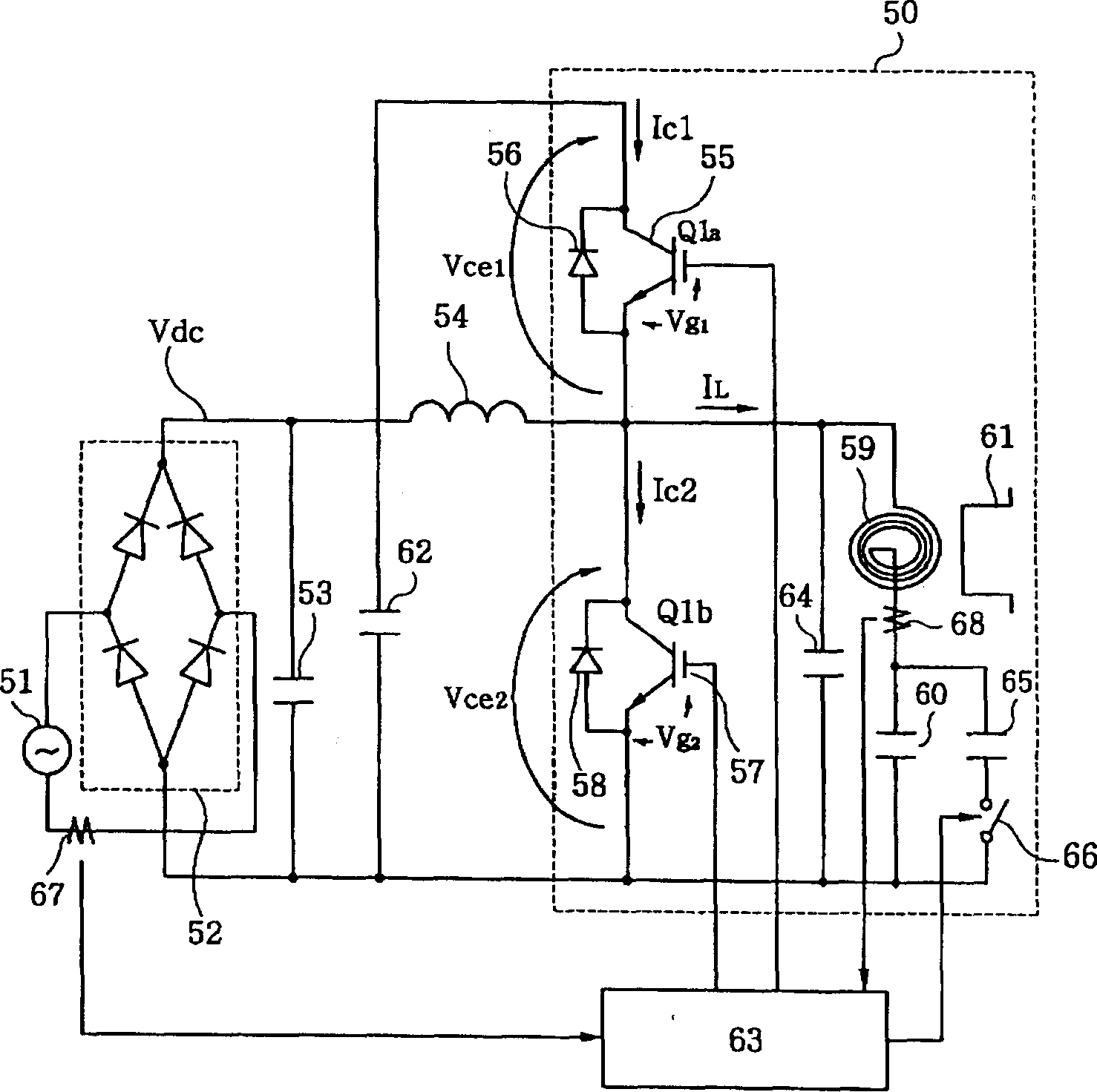
[0062] A first embodiment of the present invention will now be described with reference to the drawings.
[0063] figure 1A circuit diagram of the induction heating device of the first embodiment of the present invention is shown. The power supply 51 is a 200v low-frequency industrial AC power supply, and the power supply 51 is connected to the input end of the bridge circuit 52 . A first smoothing capacitor 53 and a series connector including a choke coil 54 and a second switching device 57 are connected between output terminals of the bridge circuit 52 . The heating coil 59 faces the aluminum pan 61 to be heated. Here, the pot 61 may be made of not only Al or Cu but also Al and Cu-based materials.
[0064] Numeral 50 denotes an inverter. The low potential terminal of the second smoothing capacitor 62 and the emitter of the second switching device 57 are connected to the negative terminal of the bridge circuit 52, and the high potential terminal of the second smoothing c...
Embodiment 2
[0102] An induction heating apparatus according to a second preferred embodiment of the present invention will now be described with reference to the accompanying drawings. Figure 5 A circuit diagram of a second preferred embodiment of the present invention is shown. The difference between the circuit configurations of the first and second embodiments of the present invention is that in the second embodiment, the first smoothing capacitor 71 and the choke coil 72 are located between the power source 51 and the bridge circuit 52 .
[0103] The operation of the second embodiment of the present invention will now be described. Numeral 50 denotes an inverter, and a control circuit 63 turns on and off the first and second switching means 55, 57 respectively as in the first embodiment of the present invention so as to obtain required input power. in the first embodiment figure 1 , when the first switching device 55 is turned on, current flows through the heating coil 59 and at t...
Embodiment 3
[0106] An induction heating apparatus according to a third preferred embodiment of the present invention will now be described with reference to the accompanying drawings. Figure 6 The circuit structure of the third preferred embodiment of the present invention is shown. The power supply 51 is an industrial power supply, and the power supply 51 is rectified by the bridge circuit 52 and supplied to the collector of the transistor 87 via the choke coil 80 . The collector of the transistor 87 is connected to the anode of the diode 82 and the cathode of the diode 82 is connected to the first end of the smoothing capacitor 81 having a high potential. The second end of the smoothing capacitor 81 having a low potential is connected to the negative electrode of the bridge circuit 52 .
[0107] Numeral 79 denotes an inverter, and one end of the choke coil 83 is connected to the first end of the smoothing capacitor 81 and the other end of the choke coil 83 is connected to the collecto...
PUM
 Abstract
Description
Claims
Application Information
 - R&D Engineer
- R&D Manager
- IP Professional
- Industry Leading Data Capabilities
- Powerful AI technology
- Patent DNA Extraction
Browse by: Latest US Patents, China's latest patents, Technical Efficacy Thesaurus, Application Domain, Technology Topic, Popular Technical Reports.
© 2024 PatSnap. All rights reserved.Legal|Privacy policy|Modern Slavery Act Transparency Statement|Sitemap|About US| Contact US: help@patsnap.com