
Strain tuning optical fiber grating sensing demodulator

A sensor demodulator and fiber grating technology, applied in the fields of fiber optic sensing, optical measurement, and wavelength tuning of optical devices, to achieve good market prospects, easy instrumentation, and stable and reliable use

Inactive Publication Date: 2003-09-17
SHANGHAI INST OF OPTICS & FINE MECHANICS CHINESE ACAD OF SCI
View PDF0 Cites 4 Cited by
  • Summary
  • Abstract
  • Description
  • Claims
  • Application Information

AI Technical Summary

Problems solved by technology

[0008] Due to the shortcomings of the above methods, the demodulation technology in the fiber grating sensing system has become one of the main obstacles to the popularization and application of this sensing technology.

Method used


Image

  • Strain tuning optical fiber grating sensing demodulator
  • Strain tuning optical fiber grating sensing demodulator
  • Strain tuning optical fiber grating sensing demodulator

Examples


Embodiment Construction

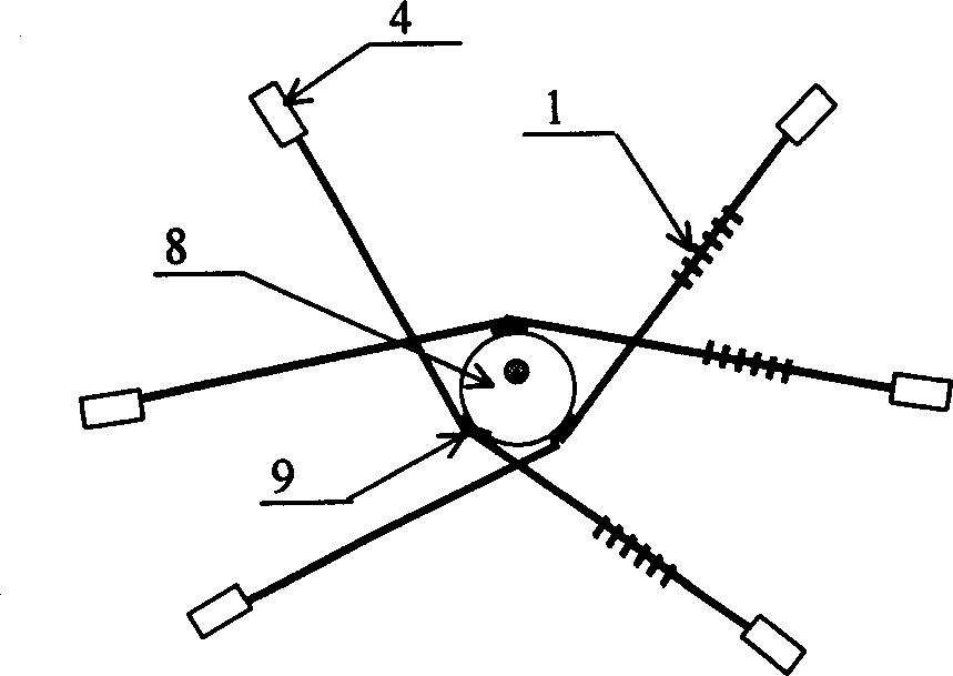
[0031] see first figure 1 and figure 2 , it can be seen from the figure that the strain-tuned fiber grating demodulator of the present invention can also be called a fiber grating lateral vibration tuning demodulator, which is composed of an optical fiber section 3 containing a fiber grating 1 and two ends 2 for fixing the optical fiber section 3 Two optical fiber holders 4, a vibrator 5 that drives the fiber segment 3 to vibrate transversely, and a casing 6 for installing and fixing the optical fiber holder 4 and the vibrator 5.

[0032] The component optical fiber 2 in the figure is a variety of optical fibers that have photorefractive properties and can be used to prepare gratings, including conventional communication optical fibers, high Ge-doped optical fibers, plastic optical fibers, and the like. The fiber grating 1 is a grating written by ultraviolet laser photorefractive method or other means. The optical fiber holder 4 is a mechanical fastener, which can be fasten...


PUM


Abstract

A strain tuned optical fibre raster sensing demodulator features that an optical fibre-segment containing optical fibre raster is fixed to a casing by two clampers at its both ends and a vibrator fordriving said optical fibre segment to vibrate is also fixed to the casing. Its advantages are simple structure and high stability and reliability.

Description

Technical field: [0001] The invention relates to a demodulator of an optical fiber grating sensor, in particular to a strain-tuned optical fiber grating sensor demodulator, which is mainly used in the technical fields of optical fiber sensing, optical measurement, and wavelength tuning of optical devices. Background technique: [0002] A fiber grating is an optical filter with narrow-band reflection characteristics fabricated on an optical fiber. Due to the elastic deformation and thermal expansion characteristics of silica fiber, as well as its thermo-optic and elastic-optic effects, it is sensitive to temperature and stress. In a certain range, this sensitivity characteristic is linear and conforms to the following relationship: Δλ ε / λ=ε(1-γ) (1) Δλ T / λ=(α+e)ΔT (2) In the formula: ε is the strain of the fiber, γ is the elasto-optic coefficient of the fiber material, α is the thermal expansion coefficient of the fiber material, ΔT is the temperature change, ...

Claims


Application Information

Patent Timeline
IPC IPC(8): G01B21/32G02B6/124G02B6/26G02F1/01G02F2/00
Inventor 方祖捷陈高庭瞿荣辉耿健新蔡海文
Owner SHANGHAI INST OF OPTICS & FINE MECHANICS CHINESE ACAD OF SCI
Learn More