
Drying installation with sheet-fed printing press

A drying device, sheet-fed technology, applied to printing machines, general parts of printing machinery, printing, etc., to achieve the effect of strengthening the drying effect

Inactive Publication Date: 2003-09-10
MANROLANAD AG
View PDF1 Cites 4 Cited by
  • Summary
  • Abstract
  • Description
  • Claims
  • Application Information

AI Technical Summary

Problems solved by technology

However, this drying principle with the help of high-voltage electrodes can only be used on fast-moving webs and cannot be used in sheet-fed printing machines in the known form

Method used


Image

  • Drying installation with sheet-fed printing press
  • Drying installation with sheet-fed printing press
  • Drying installation with sheet-fed printing press

Examples


Embodiment Construction

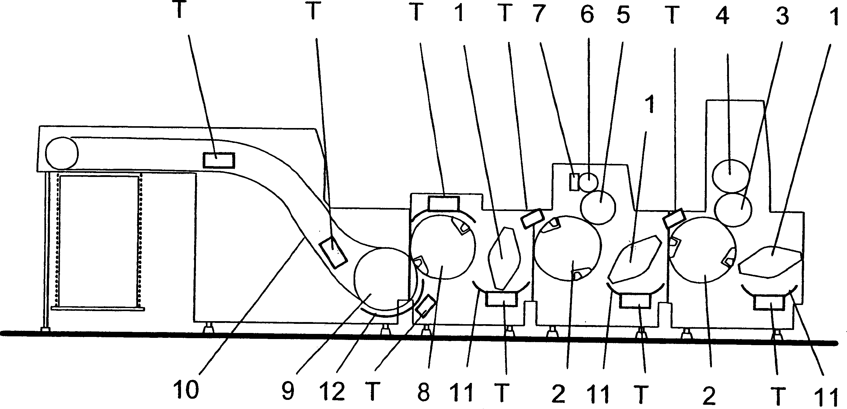
[0028] figure 1 The final printing unit of a sheet-fed offset printing press with impression cylinder 2 , blanket cylinder 3 and plate cylinder 4 is shown. Arranged upstream of the impression cylinder 2 is a transport cylinder 1 which transports the printed sheets transported from the preceding printing unit. The printed sheet conveyed by the conveying cylinder 1 is supported by the printed sheet guide 11 from both sides of the double printing surface. Behind the impression cylinder 2 of the final printing unit, an inking device and a chamber-shaped doctor blade 7 working together with the anilox ink roller 6 are arranged, and the inking device has an impression cylinder 2, a printing plate cylinder 5, a Inking roller 6. From the impression cylinder 2 of the final printing unit, the printed sheet is fed to the impression cylinder of the inking unit via the transport cylinder 1 and the associated guide 11 . The printed sheet on the impression cylinder 2 in the inking unit is...


PUM


Abstract

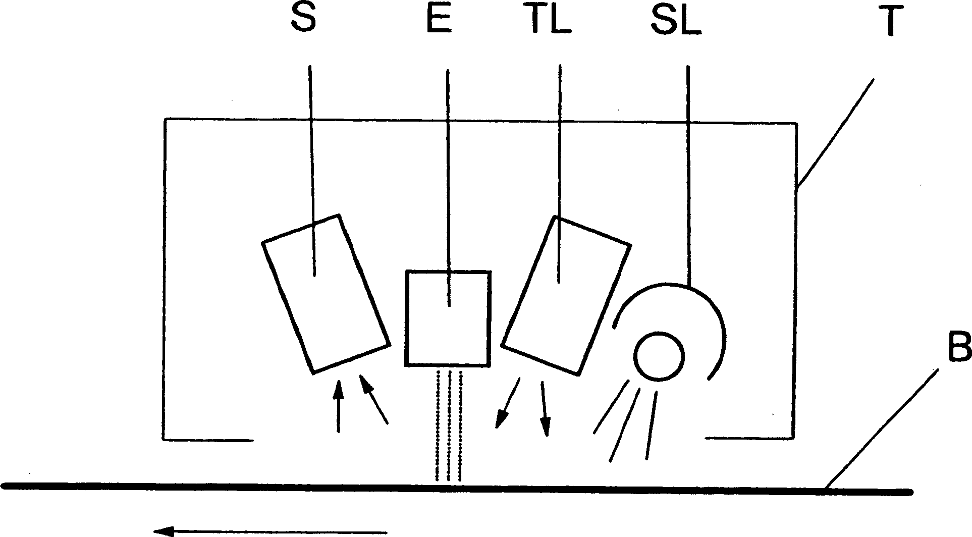
The invention relates to a drying installation within a sheet-fed printing press, comprising a device for subjecting the moving sheet to air and / or heat. The aim of the invention is to improve such a drying installation in such a manner that the drying effect is improved. To this end, an electrode (E) and a corresponding counter-electrode are associated with a high-voltage source (HV) and subjects said high-voltage source to a high-voltage depending on the operation of the sheet-fed printing press and / or the length of the sheets (B).

Description

technical field [0001] The invention relates to a drying device in a sheet-fed printing press according to the preamble of claim 1 . Background technique [0002] In a sheet-fed offset printing press, the printed sheet passes through cylinders and rollers through the individual printing presses and after the last printing press is conveyed through one or more inking units and other finishing units. The conveyance of the printed sheet from the last roller to the output table is carried out by a chain system. [0003] In order to avoid smearing of the freshly printed sheet when transporting between printing presses, between the last printing press and the output table or inking unit, drying devices are installed in many places. With these drying units, the color / ink can be dried or removed as quickly as possible, so that contact with the printed sheet guide or other fixed parts does not cause damage to the printed sheet surface and thus waste pages. [0004] On drying, solve...

Claims


Application Information

Patent Timeline
Patent Type & Authority Applications(China)
IPC IPC(8): B41F23/04F26B3/30F26B13/10F26B13/30
CPCB41F23/044
Inventor A·伊梅
Owner MANROLANAD AG
Learn More