Reciprocating compressor

A reciprocating compressor technology, applied in the field of reciprocating compressors, can solve the problems of increased cost of high-priced magnet materials, reduced compressor efficiency, and enlarged compressors

Inactive Publication Date: 2003-08-27
LG ELECTRONICS INC
View PDF0 Cites 9 Cited by
  • Summary
  • Abstract
  • Description
  • Claims
  • Application Information

AI Technical Summary

Problems solved by technology

Therefore, due to the existence of this flow resistance, the armature 22 fails to advance to the desired position, resulting in a shortened stroke of the piston 31, which reduces the efficiency of the compressor.
[0015] Additionally, if Figure 2B As shown, in the case where the front frame 41 supporting the inner stator 21A and the outer stator 21B is in a position closer to the armature 22, when the armature 22 overstrokes, the armature 22 is likely to collide with the front frame 41. damage the magnet 22B to the rear surface, or possibly increase the flux leakage between the two stators 21A and 21B
At the same time, when the front frame 41 supporting the inner stator 21A and the outer stator 21B is kept at a certain distance from the armature 22, the piston 31, the rear frame 43 and the closed casing 10 must be lengthened, resulting in an increase in the material cost of the expensive magnet. problem, increasing the compressor

Method used


Image

  • Reciprocating compressor
  • Reciprocating compressor
  • Reciprocating compressor

Examples


Embodiment Construction

[0030] A reciprocating compressor according to a preferred embodiment of the present invention will now be described with reference to the accompanying drawings.

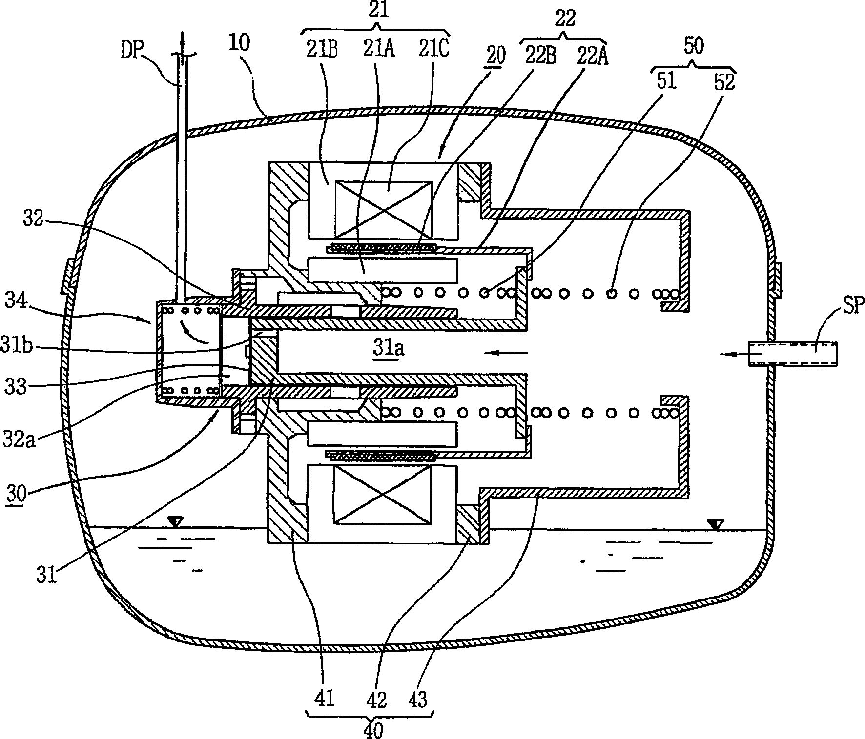
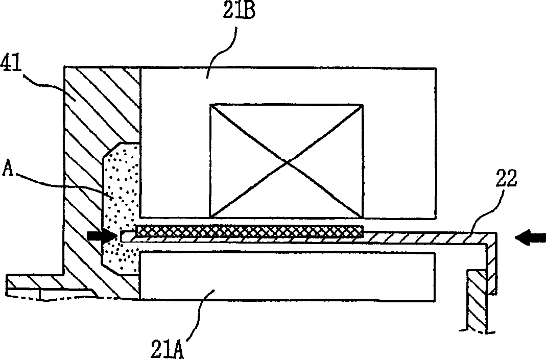
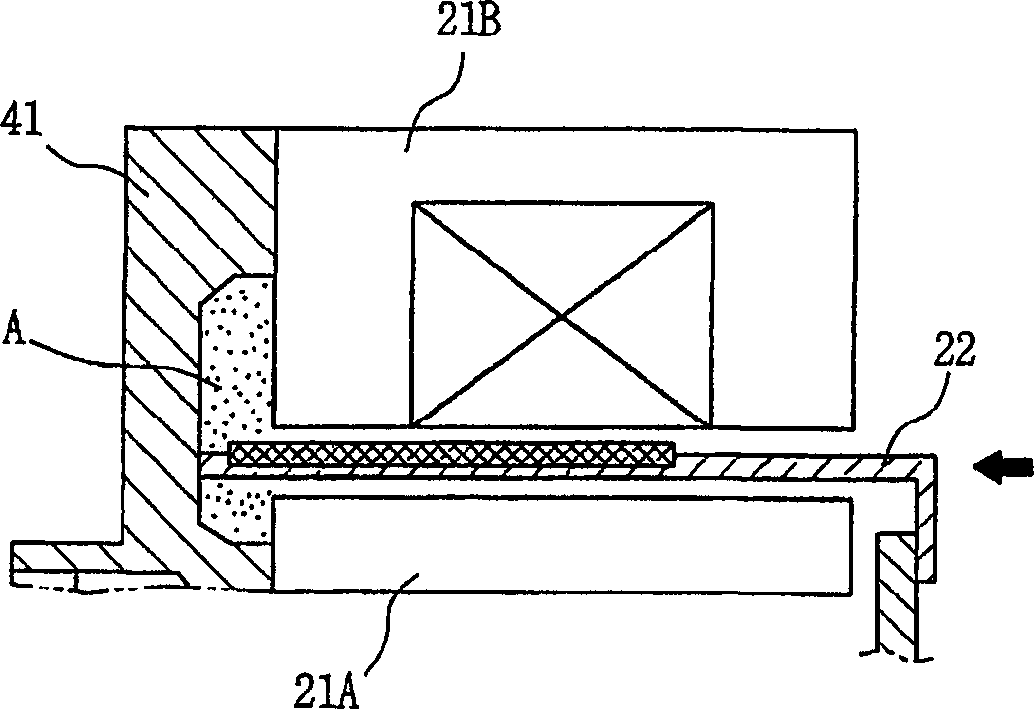
[0031] image 3 is a vertical sectional view of an example of a reciprocating compressor according to a preferred embodiment of the present invention, Figure 4 is a schematic sectional view of the main parts of the reciprocating compressor according to the preferred embodiment of the present invention, Figure 5A is a schematic sectional view of an operating state of the armature of the reciprocating compressor according to the preferred embodiment of the present invention, Figure 5B is a schematic sectional view of an operating state of the armature of the reciprocating compressor according to the preferred embodiment of the present invention.

[0032] As shown in the drawings, a reciprocating compressor of the present invention includes a closed shell 10 whose lower part is filled with lubricant and has a suct...


PUM


Abstract

A reciprocating compressor including: a closed container (10); a reciprocating motor (20) having stators and an armature (22) disposed in the air gap between the stators (21) and making a reciprocal movement; a compression unit (30) having a piston (31) combined with the armature (22) of the reciprocating motor and a cylinder fixed inside the closed container (10); a spring unit (50) elastically supporting the armature (22) of the reciprocating motor (20) in a movement direction; and a frame unit (100) supporting the reciprocating motor (20) and the compression unit (30) having a gas hole (111) at a suitable portion thereof. Accordingly, when the armature (22) of the reciprocating motor (20) makes a reciprocal movement, the gas is compressed at the end of the armature (22), so that an increase of a flow resistance is prevented. In addition, in occurrence of an over-stroke of the armature, as the step portion (112) makes a space to prevent the magnet from releasing or damaging, the reliability of the compressor is improved.

Description

technical field [0001] The invention relates to a reciprocating compressor, in particular to a reciprocating compressor which can reduce the occurrence of flow resistance when the piston reciprocates, and can prevent the armature from being damaged when the armature is overstroked. Background technique [0002] Typically, a piston reciprocates within a cylinder, and a reciprocating compressor sucks in, compresses and discharges gas. [0003] figure 1 is a vertical cross-sectional view of a conventional reciprocating compressor. [0004] like figure 1 As shown, the traditional reciprocating compressor includes a closed shell 10 whose lower part is filled with lubricant and has a suction pipe (SP) and a discharge pipe (DP) communicating with each other. The reciprocating compressor fixed in the closed shell 10 The motor 20, the compression unit 30 that is installed in the closed casing 10 and sucks, compresses and discharges gas, the frame unit 40 that supports the reciproc...

Claims


Application Information

Patent Timeline
Patent Type & Authority Applications(China)
IPC IPC(8): F04B39/00F04B35/04
CPCF04B35/045F04B39/00
Inventor 裵圭钟玄圣烈金长焕许钟泰
Owner LG ELECTRONICS INC
Why Eureka
Try Eureka