Eureka AIR delivers breakthrough ideas for toughest innovation challenges, trusted by R&D personnel around the world.

Hydraulic spiral longitudinal joint of robot

A robot and joint technology, applied in the field of longitudinal joints, can solve problems such as poor accuracy, small torque, and unstable motion.

Inactive Publication Date: 2003-08-20
CHONGQING UNIV
View PDF0 Cites 1 Cited by
  • Summary
  • Abstract
  • Description
  • Claims
  • Application Information

AI Technical Summary

Problems solved by technology

[0002] At present, there are many types of longitudinal joints in industrial robots, such as worm gear mechanism, planetary gear mechanism, rack and pinion mechanism, cycloid cylinder mechanism, etc. Most of them have large size, small torque, poor precision or unstable motion. And other issues

Method used


Image

  • Hydraulic spiral longitudinal joint of robot
  • Hydraulic spiral longitudinal joint of robot

Examples


Embodiment Construction

[0010] The specific embodiments of the present invention will be further described below with reference to the accompanying drawings.

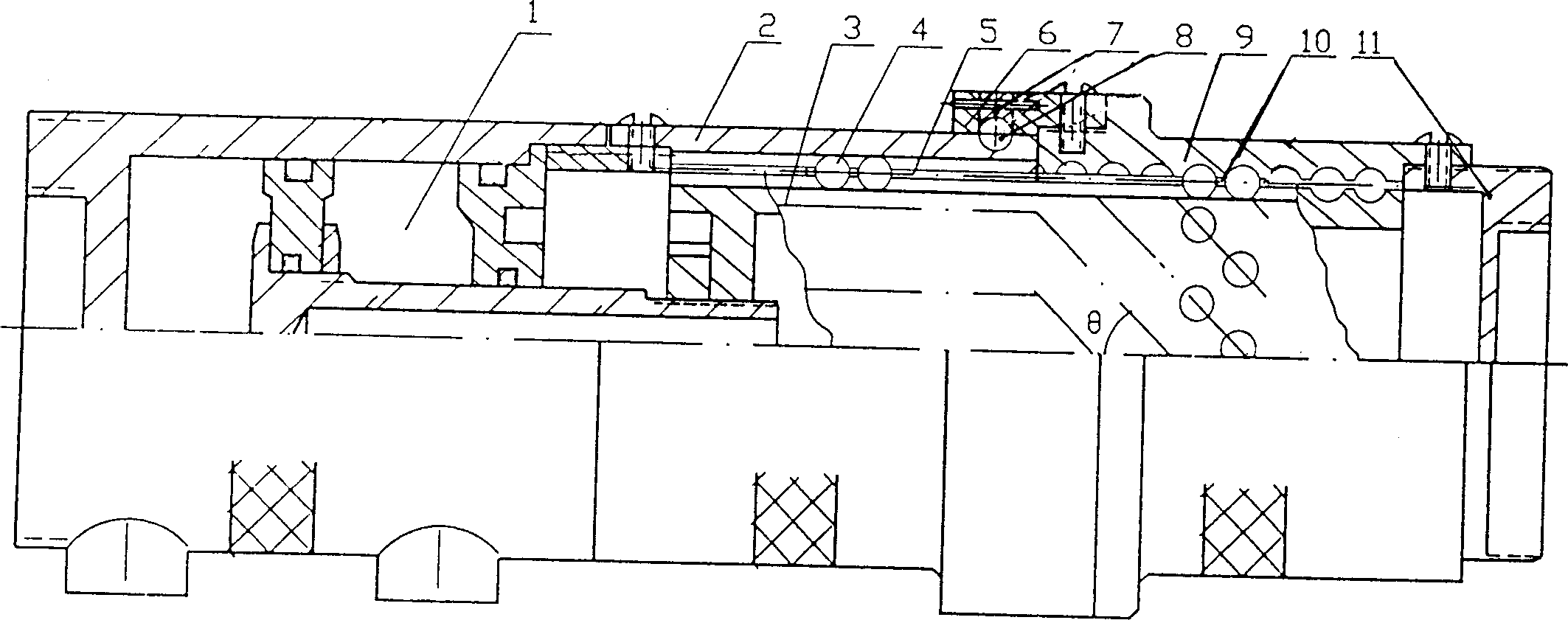
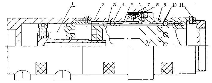
[0011] In the drawings, the rolling spline pair includes a spline sleeve (2), a spline shaft (3) and a steel ball (4) in the spline groove, wherein the steel ball is also located in the hole of the synchronous sleeve. The synchronous sleeve with holes ensures the synchronization of the steel ball movement, so that the steel balls can move forward and backward in an orderly manner in their respective grooves. The design makes the steel balls just move to the two end faces of the pair, thus eliminating the need for complicated return. bead body. Part (1) is an oil cylinder. When the oil cylinder enters the oil, the piston rod pushes the shaft (3) to move axially. The shaft (3) is composed of a straight spline section and a helical section. Since the spline sleeve (2) is fixed on the cylinder up, stay still. Therefore, the effect of the rolling...


PUM


Abstract

The present invention relates to longitudinal robot joint, which includes oil cylinder for driving, multiple rollling screw pair, rolling spline pair and output terminal. The longitudinal robot joint features that the rolling spline pair has spline shaft connected to the piston rod of the oil cylinder and spline hoursing connected to the oil cylinder liner to make the spline possess only axial motion and bear the counteractive force moment; that the multiple rolling spline pair has screw shaft integrated with the spline shaft and screw housing connected to the outer terminal to complete the conversion from the linear motion of oil cylinder to rotation motion; and that these is a thrust bearing pair between the spline housing and the screw housing to make the screw housing capable of swinging only around its axis.

Description

Technical field: [0001] The invention relates to a longitudinal joint for a robot to use an oil cylinder to drive a rolling helical transformation. Background technique: [0002] At present, there are many types of longitudinal joints in industrial robots, such as worm gear mechanism, planetary gear mechanism, rack and pinion mechanism, cycloid cylinder mechanism, etc. Most of them have large size, small torque, poor precision or unstable motion. And other issues. Invention content: [0003] The technical problem to be solved by the present invention is: use the oil cylinder as the power source, and use the rolling screw pair to directly convert the reciprocating linear motion of the oil cylinder into a rotary motion output, thereby providing a simple structure, large output torque, small size, high precision, and convenient Realize generalization, modularization and standardization of the robot hydraulic screw longitudinal joint. [0004] In order to solve the above-men...

Claims


Application Information

Patent Timeline
IPC IPC(8): B25J17/02
Inventor 梁锡昌王光建
Owner CHONGQING UNIV
Why Eureka
Eureka Blog
Learn More