Braking device of motor vehicle

A technology of brake device and exhaust brake valve, which is applied in the direction of brake transmission device, brake, vehicle parts, etc., can solve the problems of difficult to achieve reasonable control and difficult for drivers to adapt to.

Inactive Publication Date: 2003-08-13
RUILI GROUP
View PDF0 Cites 6 Cited by
  • Summary
  • Abstract
  • Description
  • Claims
  • Application Information

AI Technical Summary

Problems solved by technology

The above-mentioned braking methods all need to be manipulated by hand or foot alone, so it is difficult for the driver to adapt, and it is difficult to achieve reasonable manipulation

Method used


Image

  • Braking device of motor vehicle
  • Braking device of motor vehicle

Examples


Embodiment Construction

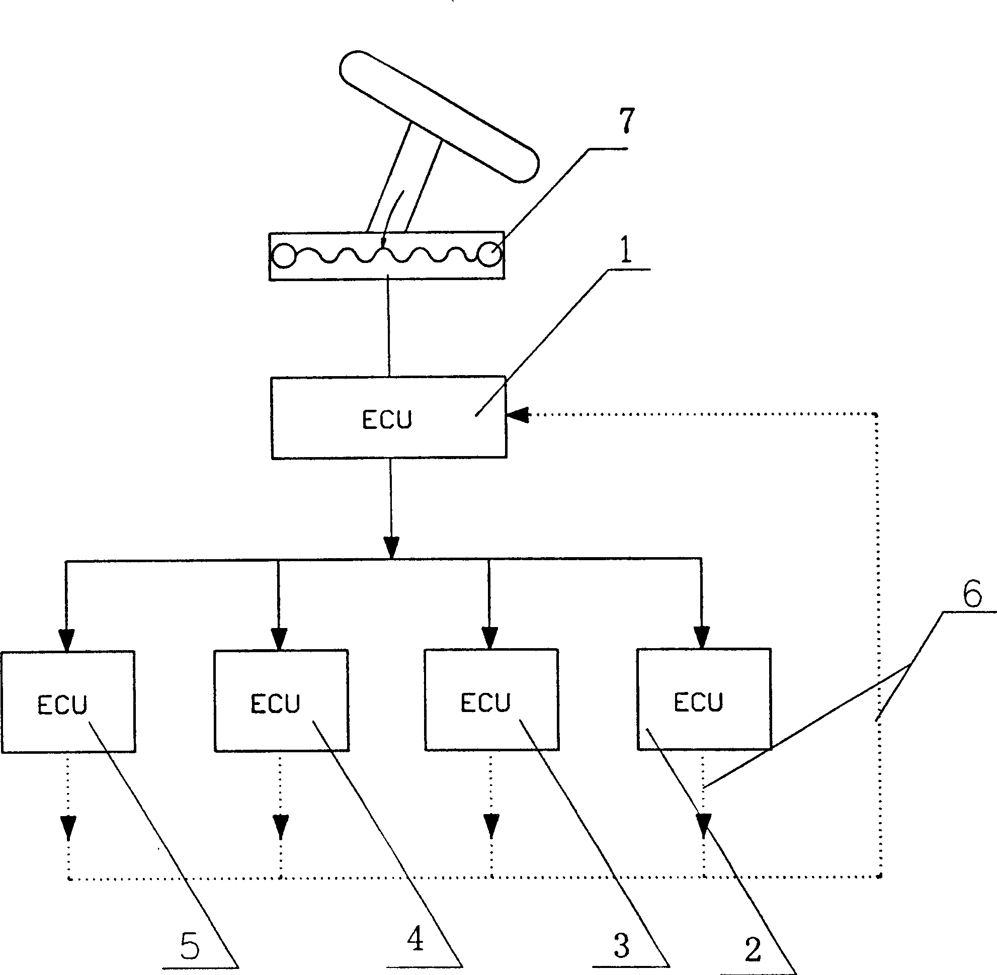
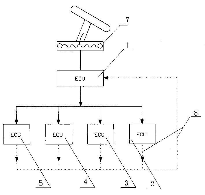
[0006] The accompanying drawings have shown the structural principles of the present invention, and the relevant details of its embodiments will be further described below in conjunction with the schematic diagrams. The brake device of the motor vehicle has an anti-lock mechanism 2, an electromagnetic retarder 3, an engine fuel pump 4 and an exhaust brake valve 5, and a brake distributor 1 is arranged on the brake device. The distributor 1 is electrically connected with the anti-lock mechanism 2, the electromagnetic retarder 3, the engine fuel pump 4 and the exhaust brake valve 5 respectively, and the brake device is also provided with an electronic pedal 7, and the electronic pedal 7 Electrically connect the electronic controller (ECU) 1 on the anti-lock mechanism 2, electromagnetic retarder 3, engine fuel pump 4 and exhaust brake valve 5 through the electronic controller 1 on the brake distributor 1 , the electronic controller 1 on the anti-lock mechanism 2, the electromagne...


PUM


Abstract

A brake unit of motor-driven vehicle has a braking distributor electrically connected with anti-blocking mechanism, electromagnetic buffer, fuel oil pump of engine and exhaust braking valve, and an electronic pedal electrically connected to the electronic controllers of said unit via the electronic controller of braking distributor. Its advantages are simple structure and high stability and reliability.

Description

technical field [0001] The invention relates to a motor vehicle braking device, in particular to the invention that the motor vehicle braking device realizes vehicle braking through an electronic controller. Background technique [0002] In the prior art, the braking devices of motor vehicles generally adopt air brakes or hydraulic brakes, and the brake pads and friction pads are subjected to external pressure to generate friction to decelerate and brake the motor vehicle. Since these are all contact mechanical brakes, their service life and working performance are reduced due to the increase in the number of times the friction pads are used, which brings danger to the vehicle and requires frequent replacement of the friction pads, which brings inconvenience to the driver. In order to prevent the danger of the vehicle wheels being locked by the brake hub when the vehicle brakes on wet roads, some vehicles are currently equipped with ABS anti-lock brakin...

Claims


Application Information

Patent Timeline
Patent Type & Authority Applications(China)
IPC IPC(8): B60T13/10B60T13/74
Inventor 陶保建
Owner RUILI GROUP
Why Eureka
Try Eureka