Hand-held cable continuity test device and system and test method for rail vehicle
A technology for rail vehicles and continuity testing, which is used in measuring devices, measuring electricity, measuring electrical variables, etc., and can solve problems such as large size, low efficiency, and complicated principles and wiring.
- Summary
- Abstract
- Description
- Claims
- Application Information
AI Technical Summary
Problems solved by technology
Method used
Image
Examples
Embodiment 1
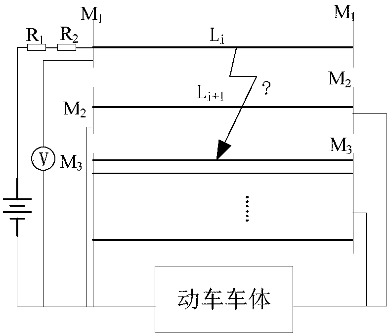
[0079] A hand-held cable conduction test device for a rail vehicle, the rail vehicle includes at least two cables to be tested and a car body, including: at least three busbars, at least one busbar switching module, N grounding switching modules, switching Control the driving circuit and the grounding port used to connect with the vehicle body; N is the number of busbars, and N is a positive integer; the at least three busbars include an idle busbar, and the remaining busbars are test buses;
[0080] The switching control drive circuit is used to send a switching signal;
[0081] Each of the bus switching modules includes an enable input terminal for receiving switching signals, M cable connection terminals and M pairs of switching contacts, two of each pair of switching contacts are respectively connected to the idle bus and one of the The test busbar, the test busbars connected by different switching contacts are different, and the enable input terminal is connected to the M...
Embodiment 2
[0119] The difference from the above embodiment is that the test circuit as the master device also includes M×2 resistors and M resistor switching modules;
[0120] Every two resistors are connected in series in one of the bus power supply circuits, each resistance switching module includes an enable input terminal for receiving a switching signal and a pair of switching contacts, each resistance switching module communicates with each through a pair of switching contacts One resistor in the two bus power supply circuits is connected in parallel to form a resistance parallel circuit, and the enable input terminal of the resistance switching module is connected to the switching contact of the resistance switching module and the switching control drive circuit, for when a switching signal is received, Switching between on and off states of the resistor parallel circuit.
[0121] In this embodiment, when testing the cable short circuit or conduction resistance, the resistance con...
PUM
 Abstract
Description
Claims
Application Information
 - R&D
- Intellectual Property
- Life Sciences
- Materials
- Tech Scout
- Unparalleled Data Quality
- Higher Quality Content
- 60% Fewer Hallucinations
Browse by: Latest US Patents, China's latest patents, Technical Efficacy Thesaurus, Application Domain, Technology Topic, Popular Technical Reports.
© 2025 PatSnap. All rights reserved.Legal|Privacy policy|Modern Slavery Act Transparency Statement|Sitemap|About US| Contact US: help@patsnap.com


