Flash device, camera with said flash device and control method for said camera

A technology of a flash device and a camera, which is applied in the field of flash technology and can solve the problems of complex structure, manual change of irradiation direction, and enlargement of the camera.

Inactive Publication Date: 2003-06-25
OLYMPUS OPTICAL CO LTD
View PDF0 Cites 5 Cited by
  • Summary
  • Abstract
  • Description
  • Claims
  • Application Information

AI Technical Summary

Problems solved by technology

[0008] In addition, although the reflector part can be rotated, it is too troublesome to manually change the irradiation direction every time the focal length of the photographic lens is changed. The problem of exposure in the direction of illumination
[0009] In addition, the flash device that changes the illumination range by moving the flash discharge tube and reflector back and forth and changing the irradiation angle has a complicated structure.
In addition, although the built-in flash device can move the reflector like the external flash device, it cannot ensure the necessary space, which will lead to an increase in the size of the camera, so this function cannot be used.

Method used


Image

  • Flash device, camera with said flash device and control method for said camera
  • Flash device, camera with said flash device and control method for said camera
  • Flash device, camera with said flash device and control method for said camera

Examples


Embodiment Construction

[0028] Embodiments of the present invention will be described in detail below with reference to the drawings.

[0029] First, the concept of the flash device of the present invention will be described.

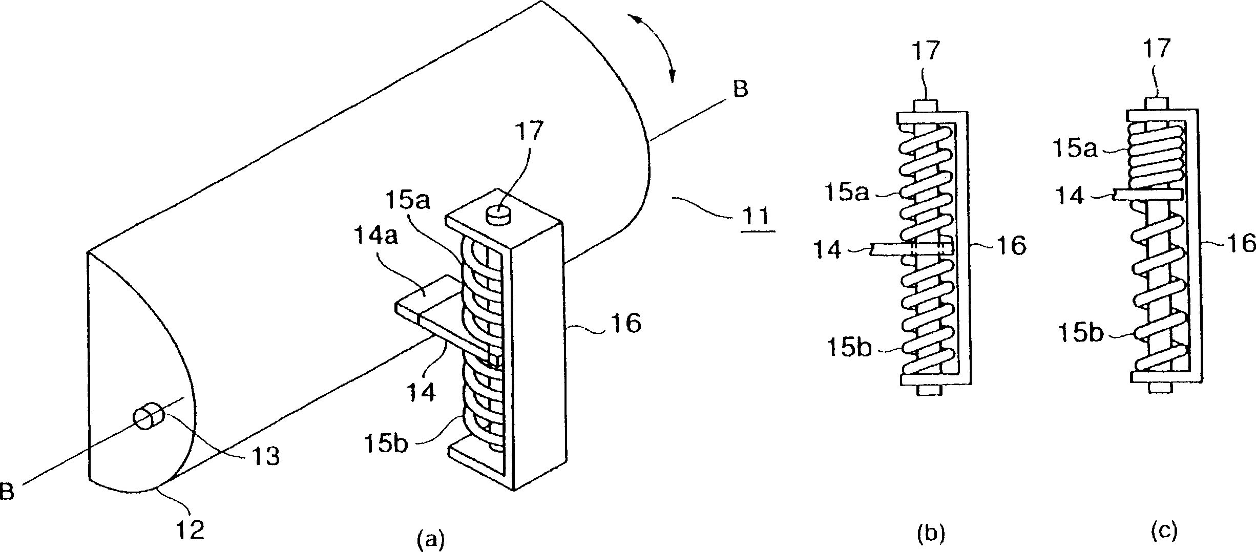
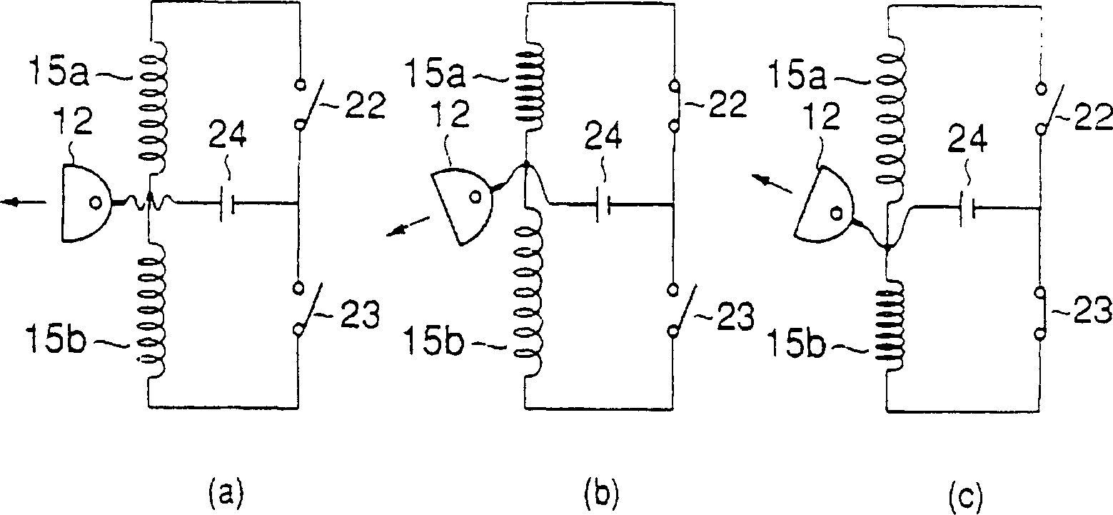
[0030] In the flash device of the present invention, the irradiation direction of the flash is changed by shaking (rotating) the reflective umbrella of the flash in the device up and down. The umbrella estimates the imaging range based on distance measurement data, and is rotated by applying a voltage to a drive spring made of shape memory alloy to change to an appropriate irradiation direction.

[0031] Figure 5 (a) to (c) show the relationship between the shooting range of the taking lens and the lighting range of the flash. Here, the center of the illumination range of the flash is taken as the irradiation direction of the flash.

[0032] exist Figure 5 In the example shown in (a), a reflector 2 for a flash of a flash device is provided above a single-focus photograph...


PUM


Abstract

A stroboscopic device is embarked on a camera. Because the irradiating direction of strobe light is fixed, there is a problem that a part of photographed object presented at super close distance can not be illunimated to darkle. Although the irradiating direction of strobe light can be changed manually, it is inconvenient. The invention relates to a stroboscopic device equipped with a function of changing the irradiating direction of strobe light. A driving spring made of shape memory alloy is coupled with the rear part of a reflector turnably supported so that the irradiating direction of the strobe light can be changed. The driving spring is applied with voltage in accordance with range-finding data and focus data and makes the reflector turn to let the illuminating range of the strobe light cover the camera coverage of the camera optical system.

Description

technical field [0001] The present invention relates to a flash device (strobo device), a camera equipped with the flash device (Limera) and a control method of the camera, and particularly relates to a flash technology capable of changing the irradiation direction of the flash to illuminate the shooting range. Background technique [0002] Generally, when the image of the subject is dark such as night photography, it is necessary to use the auxiliary light. Auxiliary light ranges from light for lighting to various types of light, but it is usually flashed using a flash device, that is, using a flash. Such flash devices include a built-in type that is built into a camera, and an external type that is separately attached to an accessory or the like from the camera. [0003] In addition, the photographic range of a camera equipped with a photographic lens with variable focal length, that is, a so-called zoom lens, can be arbitrarily determined by the photographer. [0004] I...

Claims


Application Information

Patent Timeline
Patent Type & Authority Applications(China)
IPC IPC(8): G03B15/05G03B13/20
Inventor 渡边小百合
Owner OLYMPUS OPTICAL CO LTD
Why Eureka
Try Eureka