Push-button steering wheel lock

A steering wheel, button technology, used in building locks, anti-theft vehicle accessories, vehicle parts, etc.

Inactive Publication Date: 2003-06-04
MASTER LOCK CO INC
View PDF4 Cites 1 Cited by
  • Summary
  • Abstract
  • Description
  • Claims
  • Application Information

AI Technical Summary

Problems solved by technology

However, a key is required to move the pushbutton lock from the locked position to the unlocked position

Method used


Image

  • Push-button steering wheel lock
  • Push-button steering wheel lock
  • Push-button steering wheel lock

Examples


Embodiment Construction

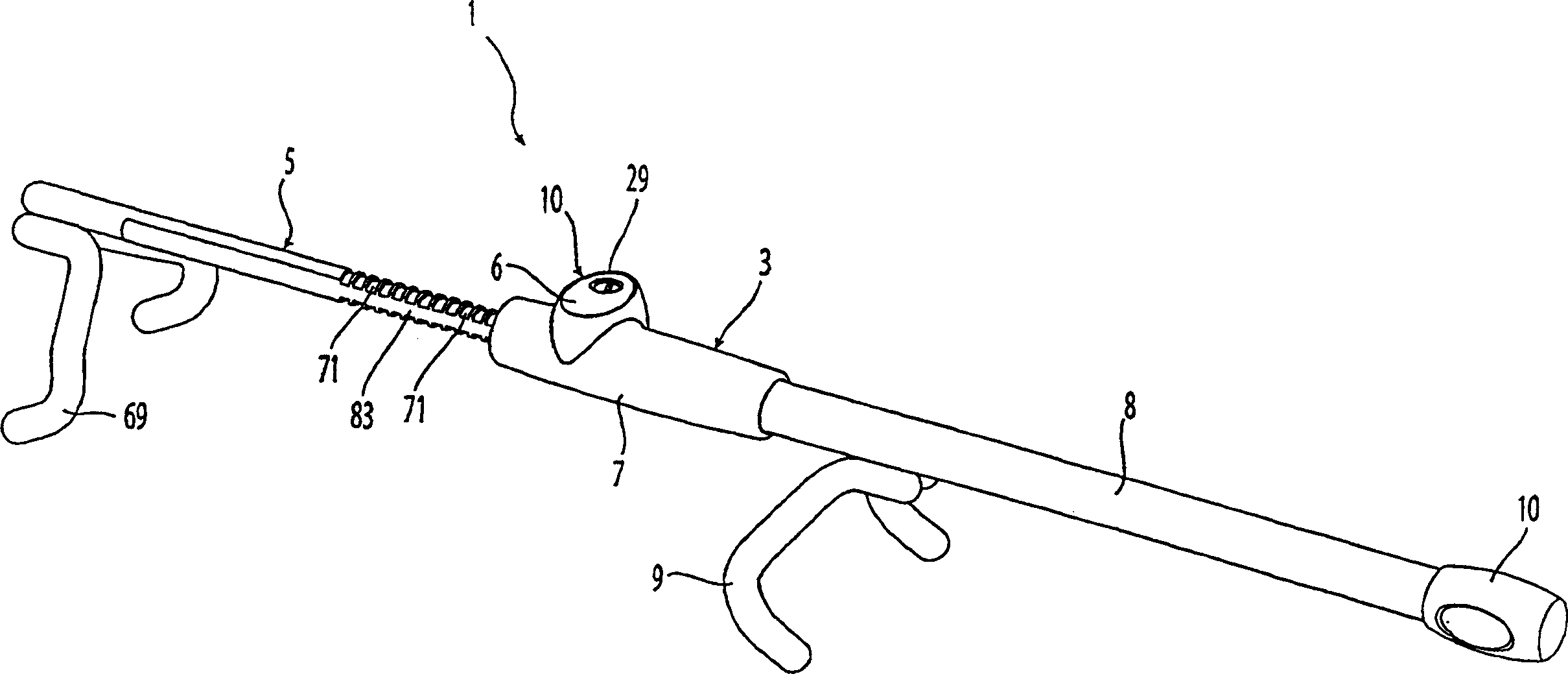
[0024] first reference figure 1 , The push button steering wheel lock 1 according to the present invention includes a lock 3 and a handle 5 . The lock 3 comprises a button assembly 6 and a housing 7 to which a hollow extension sleeve member 8 is attached. The first engagement part 9 is attached to the sleeve part 8 . The first engaging part 9 is used for engaging with the steering wheel to fix the steering wheel lock 1 thereon. Preferably, the first engaging means 9 are two fork-shaped hooks. A rubber grip 10 is provided on the sleeve part 8 to create a handle for gripping the push-button steering wheel lock 1 .

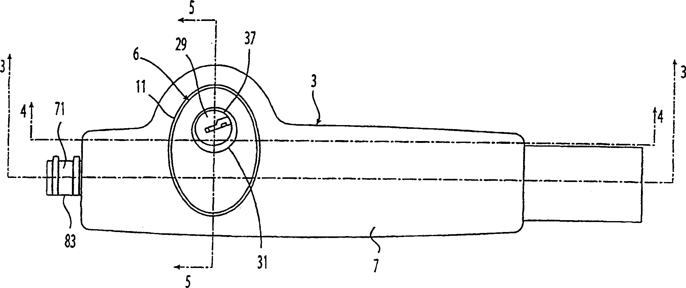
[0025] Such as Figure 2-9 As best shown in , the housing 7 includes a first chamber 11 and a second chamber 13 . The first chamber 11 is cylindrical and has a non-circular cross-section, for example an oblong or elliptical cross-section. The second chamber 13 is also cylindrical and also has a non-circular cross-section. The first and second chambers intersec...


PUM


Abstract

A push-button steering wheel lock for attachment to an automobile steering wheel is provided having a housing and a push-button assembly disposed in the housing. The assembly is positioned in either a locked position for securing the steering wheel lock to the steering wheel or an unlocked position. In the locked position, the push-button lock assembly engages a rod slideably disposed in the housing to prevent movement of the rod with respect to the housing. The push-button assembly also includes two levers, one each on either side of the assembly to engage two surfaces within the housing to retain the push-button assembly in the locked position and also to retain the push-button assembly in the housing.

Description

Background technique [0001] Locks in the form of push buttons are known to provide the user with the ability to move the lock from an unlocked position to a locked position simply by pushing a button without the need for a key. However, a key is required to move the push button lock from the locked position to the unlocked position. [0002] For example, US Patent No. 4,009,599 relates to a switch lock and discloses a longitudinally movable sleeve within the housing. A locking tab protrudes from the periphery of the sleeve and is received by a locking slot defined by the housing. The tab is biased to protrude from the perimeter of the sleeve. When the cover is pushed into the locked position and the tab is aligned with the locking slot, the tab snaps into the slot, thus establishing the locked position. The blade can then be withdrawn from the slot corresponding to an appropriate operation of the key. [0003] US Patent 1,369,308 relates to a locking device for automobiles...

Claims


Application Information

Patent Timeline
IPC IPC(8): B60R25/02
CPCB60R25/0225Y10S70/20Y10T70/5894Y10T70/7712Y10T70/5765Y10T70/7576Y10T70/5841B60R25/02121
Inventor G·梅克马G·罗哈特吉
Owner MASTER LOCK CO INC
Why Eureka
Try Eureka