
Data recording device

A data recording, data technology, used in data recording, optical recording heads, optical recording systems, etc.

Inactive Publication Date: 2003-04-09
PIONEER CORP
View PDF1 Cites 3 Cited by
  • Summary
  • Abstract
  • Description
  • Claims
  • Application Information

AI Technical Summary

Problems solved by technology

However, the peak hold circuit is a large-scale circuit

Method used


Image

  • Data recording device
  • Data recording device
  • Data recording device

Examples


no. 1 example

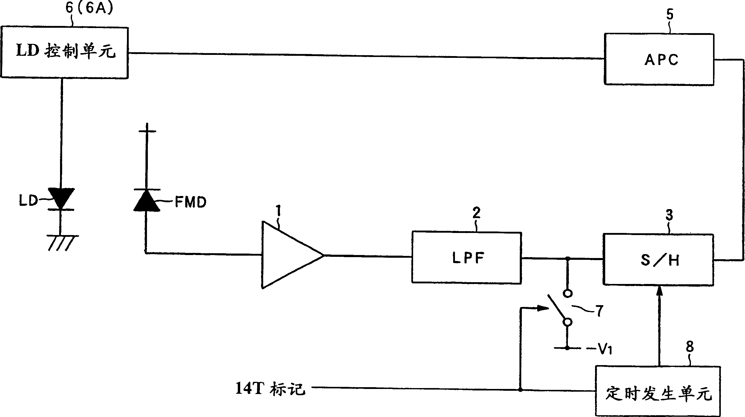
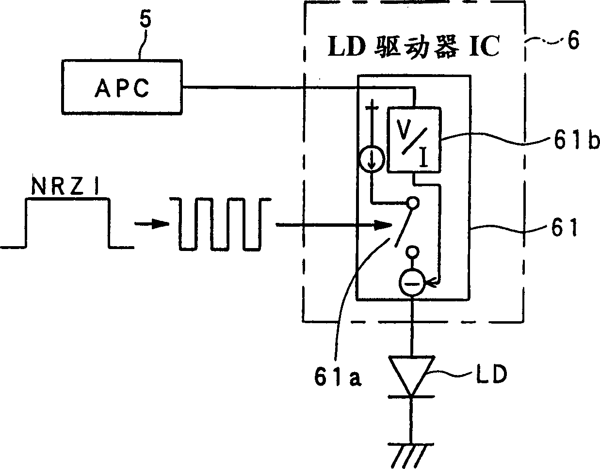
[0036] The following will refer to figure 1 4 to 4 describe the first embodiment of the data recording apparatus of the present invention. figure 1 is a block diagram showing the configuration of the light irradiation control unit in the data recording apparatus of the first embodiment, FIG. 2 is a block diagram showing the configuration of the laser diode control unit, FIG. 3 shows a current waveform supplied to the laser diode, and FIG. 4 is A timing chart showing the waveforms of each part of the data recording device.

[0037] Such as figure 1 As shown, the data recording apparatus of the first embodiment includes a laser diode LD, which applies laser light to an optical disk (not shown); a front monitor diode FMD, which detects the intensity of light emitted from the front exit side of the laser diode LD; A preamplifier 1, which amplifies the detection signal of the front monitor diode FMD; a low-pass filter 2, which consists of a main passive circuit receiving the outp...

no. 2 example

[0055] will now refer to Figures 5 to 7 A second embodiment of the data recording device of the present invention will be described. The data recording apparatus of the second embodiment is an apparatus for writing data in a DVD-R which is a data recording medium to which only data addition is possible.

[0056] Figure 5 is a block diagram showing the configuration of a light irradiation control unit in the data recording device of the second embodiment; FIG. 6 is a timing chart showing waveforms of respective parts of the device; and Figure 7 is a timing diagram representing another example operation. In addition, the same reference numerals will be used for the same elements as those in the first embodiment, and their description will not be repeated.

[0057] Such as Figure 5 As shown, the data recording device of the second embodiment includes a band conversion unit 9 for converting the filtering band of the low-pass filter 2 . The signal output from the timing ge...


PUM


Abstract

An data recording apparatus comprises a laser diode (LD) applying light to a recording medium to record data, a front monitor diode (LMD) detecting the intensity of light emitted from the laser diode (LD), a switch (7) for switching to said lowpass filter (2) in the operating state during the time period over which a signal of 14T mark is recorded, a lowpass filter (2) inputted a signal which is outputted from a front monitor diode (FMD), and a sampling / holding unit (3) sampling the output signal outputted from the lowpass filter (2). The intensity of light emitted from the laser diode (LD) based on the output signal sampled by the sampling / holding unit (3).

Description

technical field [0001] The present invention relates to a technical field related to a data recording device for recording information by exposing a data recording medium to light, and more particularly, to a data recording device capable of properly controlling the intensity of light. technical background [0002] In recent years, when a data recording medium capable of recording / erasing data (ie, DVD-RW) is exposed to laser light to perform recording, two methods are used to maintain a constant laser intensity. One of the methods is a method of detecting a change in temperature of a laser diode that emits laser light, thereby supplying a certain amount of current in accordance with the temperature change. Another method is a method of providing a front monitor for detecting the intensity of laser light, performing peak hold on a detection signal from the front monitor for control, thereby maintaining a constant peak value. [0003] However, in the former method, the emiss...

Claims


Application Information

Patent Timeline
Patent Type & Authority Applications(China)
IPC IPC(8): G01J1/32G11B7/00G11B7/0045G11B7/0055G11B7/125
CPCG11B7/00456G11B7/0062G11B7/1263
Inventor 佐佐木仪央田中博之内野裕行上田整
Owner PIONEER CORP
Learn More