
Light source module

A light source module and light incident surface technology, which is applied in light guides, optics, optical components, etc., can solve problems affecting the uniformity of light output from the light source module, achieve uniform brightness, avoid splicing bright lines, and avoid edge bright lines.

Inactive Publication Date: 2011-09-14
苏州茂立光电科技有限公司
View PDF7 Cites 2 Cited by
  • Summary
  • Abstract
  • Description
  • Claims
  • Application Information

AI Technical Summary

Problems solved by technology

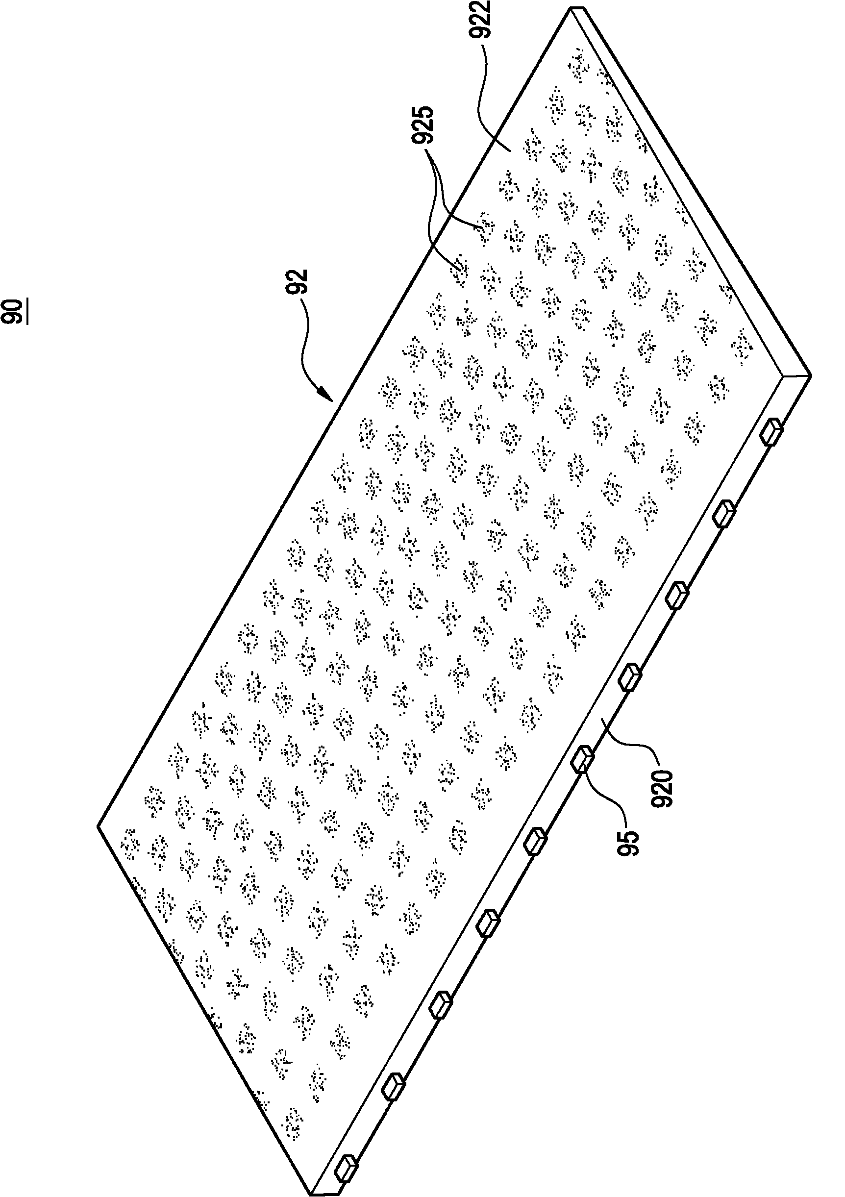
In order to make the light emitting surface 922 emit light with uniform brightness, the light guide plate 92 must guide the light projected into the light guide plate 92 from the light incident surface 920 by the light emitting unit 95 as close as possible to the rear end surface of the light guide plate 92 926, because the rear end surface 926 is not provided with the light guide unit 925 to adjust the light, so part of the light is directly refracted through the rear end surface, so that the light intensity of the rear end surface 926 is significantly greater than that of the light exit surface The light intensity of 922 will result in the generation of a light-emitting bright line at the edge; and, when the light guide plates 92 are spliced, a clearly visible splicing bright line will be produced at the junction of the two adjacent light guide plates 92, which will affect the overall light source Light uniformity of the module

Method used


Image

  • Light source module
  • Light source module
  • Light source module

Examples


Embodiment Construction

[0016] Below in conjunction with accompanying drawing and specific embodiment the present invention is described in further detail:

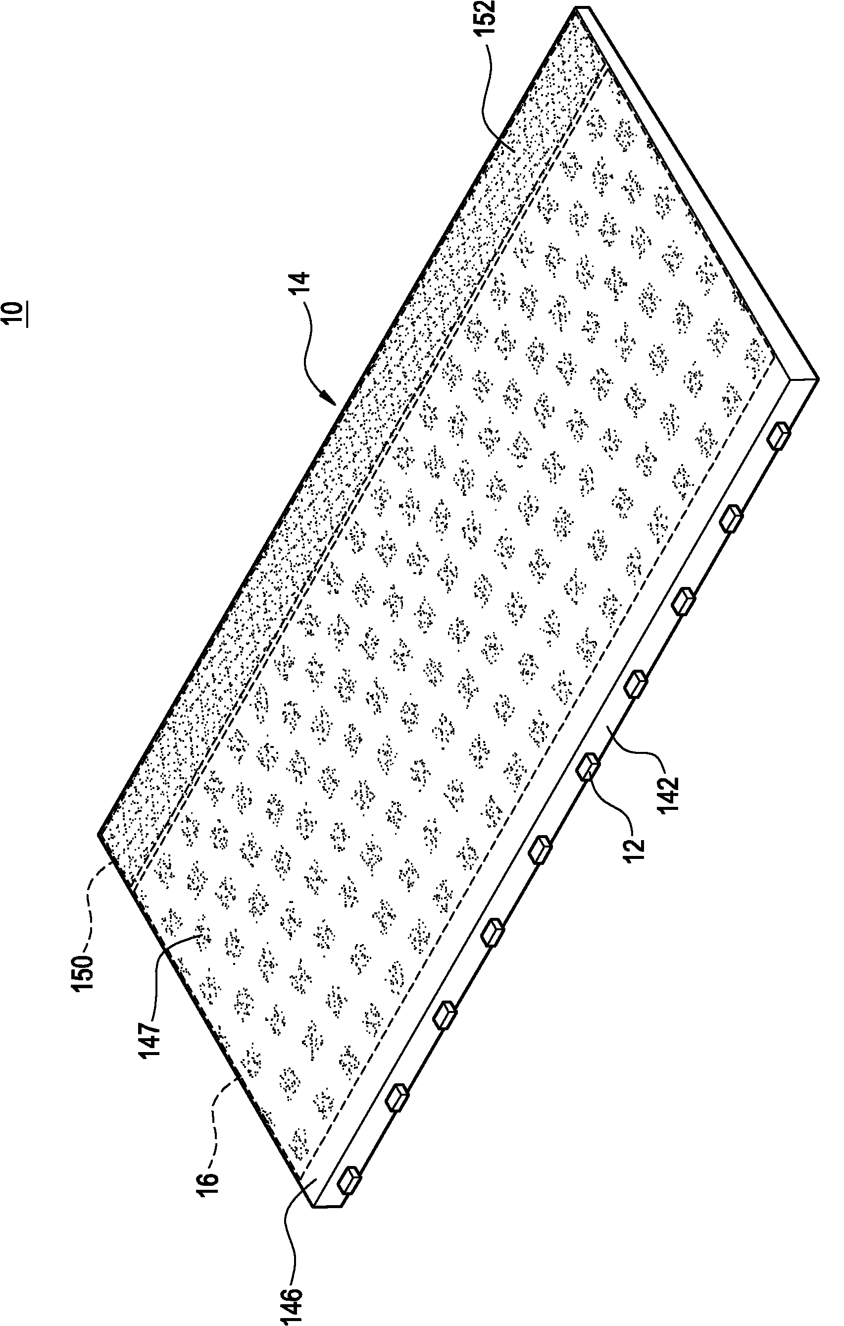
[0017] The present invention provides a light source module. The light source module includes at least one light emitting unit and a light guiding component. The light guiding component and the light emitting unit jointly define an effective light output area. The light guide body includes a light incident surface, a light exit surface, a bottom surface, a rear end surface and a first edge area. The light incident surface is provided with the light-emitting unit, and the light-emitting units respectively project light toward the light incident surface; the light exit surface is adjacent to one side of the light incident surface; the bottom surface is provided at the place corresponding to the effective light exit area. A plurality of light guide units with a first setting depth; the rear end surface is opposite to the light incident surface and ...


PUM


Abstract

The invention relates to a light source module, which comprises at least one light emitting unit and a light guide component, wherein the light guide component comprises a light guide body; the light guide body is an effective light emergence area which is defined together with the light emitting unit; the light guide body comprises a light incidence plane, a light emergence plane, a bottom surface, a rear end face and a first edge area; the light emitting unit is arranged on the light incidence plane and emits a light ray toward the light incidence plane; the light emergence plane is adjacent to one side of the light incidence plane; the bottom surface is opposite to the light emergence plane; an inclined angle is formed between the bottom surface and the light emergence plane; a plurality of light guide units having first set depths are arranged at a position, corresponding to the effective light emergence area, of the bottom surface; the rear end face is opposite to the light incidence plane and adjacent to the light emergence plane and the bottom surface; the first edge area is positioned between the effective light emergence area and the rear end face; and at least one first optical micro structure having a second set depth is arranged at the position, corresponding to the first edge area, of the bottom surface.

Description

technical field [0001] The present invention relates to a light source module, in particular to a structure of a light guide assembly in the light source module. Background technique [0002] Cooperate with reference Figure 1A and Figure 1B , are respectively a perspective view and a cross-sectional view of a light source module in the prior art. The light source module 90 includes a light guide plate 92 and a plurality of light emitting units 95 . The light guide plate 92 includes a light incident surface 920 , a light output surface 922 , a bottom surface 924 and a rear end surface 926 . The light-incident surface 920 is used for disposing the light-emitting units 95 , and the light-emitting units 95 respectively project light toward the light-incident surface 920 . The light emitting surface 922 is adjacent to the light incident surface 920 , the bottom surface 924 is adjacent to the light incident surface 920 and is inclined at an angle with the light emitting surfac...

Claims


Application Information

Patent Timeline
Patent Type & Authority Applications(China)
IPC IPC(8): F21V8/00
Inventor 刘煌竣
Owner 苏州茂立光电科技有限公司
Learn More