Method and apparatus for absorbing matrix

A substrate and equipment technology, which is used in metal processing equipment, workpiece clamping devices, semiconductor/solid-state device manufacturing, etc., can solve the problems of long holding time, large residual holding force, and difficult separation of substrates.

Inactive Publication Date: 2003-04-02
NISSIN ION EQUIP CO LTD
View PDF0 Cites 6 Cited by
  • Summary
  • Abstract
  • Description
  • Claims
  • Application Information

AI Technical Summary

Problems solved by technology

Also, in this case, although the clamping voltage is a lower voltage V 2 , but at this constant clamping voltage Vc (voltage V 2 ) holding time is longer
Therefore, as combined with the Figure 5 As described by the middle curve C, the residual holding force is large, and it is difficult to separate the substrate 4 after the holding operation stops

Method used


Image

  • Method and apparatus for absorbing matrix
  • Method and apparatus for absorbing matrix
  • Method and apparatus for absorbing matrix

Examples


Embodiment Construction

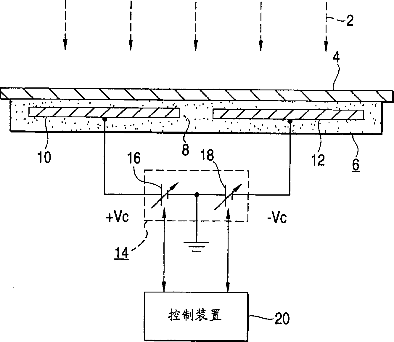
[0030] attached figure 1 is a schematic diagram showing a substrate holding device for performing the substrate holding method of the present invention. In this figure, with the prior art description (cf. Figure 4 Description) the same or equivalent parts are denoted by the same reference numerals. The following description will focus on the differences between this embodiment and the related existing equipment.

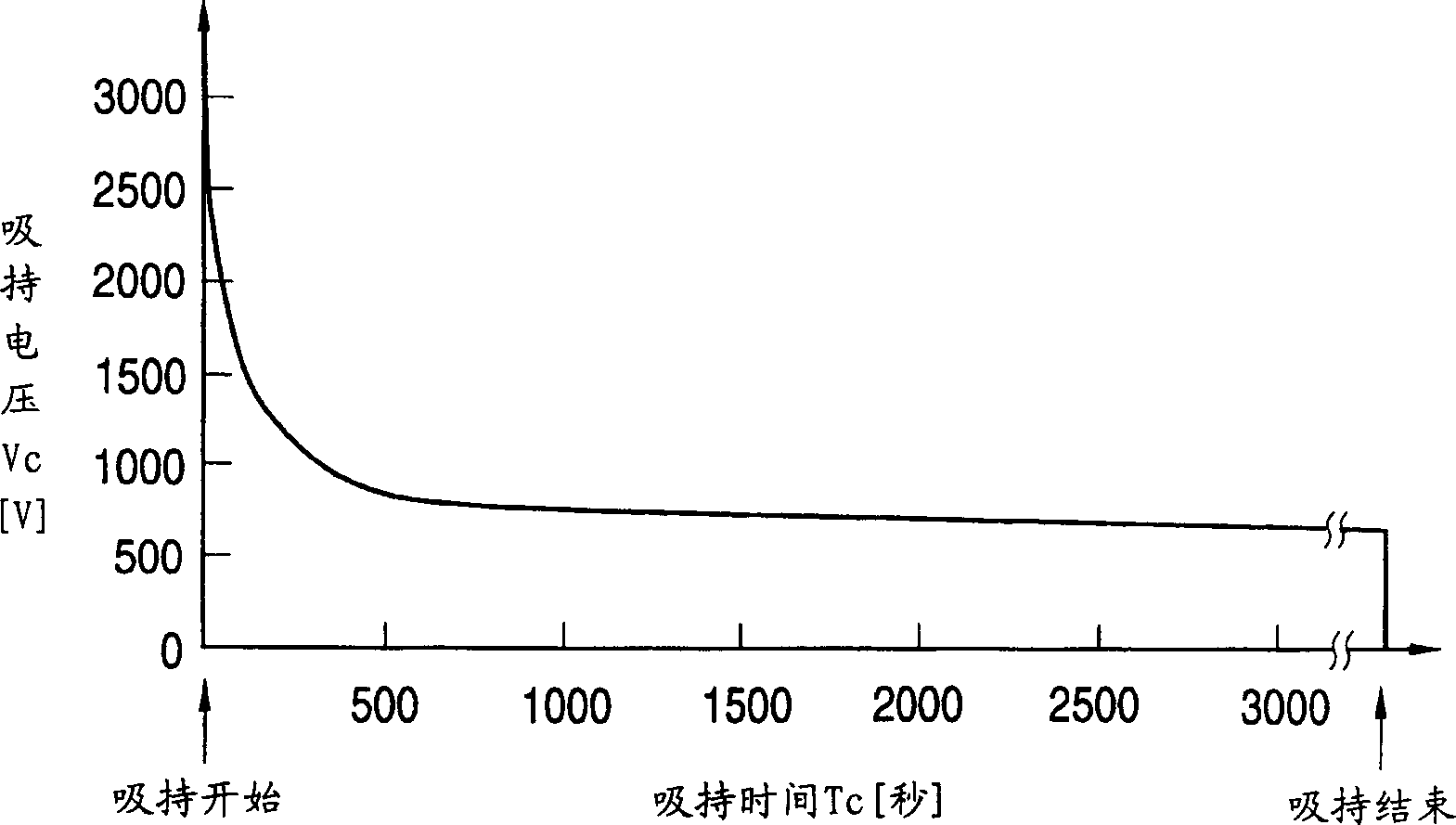
[0031] as in the attached figure 2 As in the case shown in , in this substrate holding device, after the electrostatic chuck 6 starts to hold a substrate 4, the magnitude of the holding voltage Vc is relative to the holding time Tc (that is to say, as the holding time Tc The lapse of holding time Tc) decreases smoothly exponentially. In this specification, the term "starting chucking of the substrate 4" refers to a point of time at which the substrate 4 is placed on the electrostatic chuck 6 and application of the chucking voltage Vc to the electrostatic chuck ...


PUM


Abstract

A substrate chucking method and apparatus are provided. A substrate chucking apparatus includes an electrostatic chuck for electrostatically chucking a substrate, and a DC power supply for applying a DC chucking voltage to the electrostatic chuck. An amplitude of the chucking voltage Vc is exponentially decreased with respect to a chucking time after an operation of chucking the substrate starts. Such a control of the chucking voltage variation is executed by a control device.

Description

technical field [0001] The invention relates to a method and equipment for holding a substrate. The equipment includes an electrostatic chuck for electrostatic holding and fixing of the substrate to be processed. In particular, the present invention relates to a method and apparatus for holding a substrate, which are capable of generating a sufficiently large holding force during the holding operation of the substrate, and which are easy to perform on all objects after the holding operation is completed. The matrix is ​​separated. For example, the substrate holding device can be used in an ion implanter, ion doping apparatus, ion beam etching apparatus, plasma chemical vapor deposition apparatus (plasma CVD apparatus), film forming equipment or similar equipment. Background technique [0002] in the attached Figure 4 An existing substrate holding device of this type is shown in . The substrate holding device includes a bipolar electrostatic chuck 6 and a bipolar output D...

Claims


Application Information

Patent Timeline
Patent Type & Authority Applications(China)
IPC IPC(8): B23Q3/15C23C14/50C23C16/458H01L21/02H01L21/205H01L21/265H01L21/302H01L21/3065H01L21/683
CPCH01L21/6833H01L21/02
Inventor 石田修也
Owner NISSIN ION EQUIP CO LTD
Why Eureka
Try Eureka