Handle of golf ball brassy manufacture and manufacturing device

A technology for golf balls, manufacturing devices, applied in the direction of golf balls, golf clubs, rackets, etc., capable of solving problems such as fluid outflow, lamination material curl and relaxation

Inactive Publication Date: 2003-04-02
MIZUNO CORPORATION
View PDF1 Cites 2 Cited by
  • Summary
  • Abstract
  • Description
  • Claims
  • Application Information

AI Technical Summary

Problems solved by technology

Therefore, it is difficult to supply pressure with respect to the rolling direction, and there is a problem that the laminated material tends to curl and loosen.
[0028] Furthermore, in the technique disclosed in the above publication, the pipe for introducing the fluid into the pressing surface of the winding member is damaged due to continuous reciprocating winding operation, so there is also a problem that the fluid may flow out.

Method used


Image

  • Handle of golf ball brassy manufacture and manufacturing device
  • Handle of golf ball brassy manufacture and manufacturing device
  • Handle of golf ball brassy manufacture and manufacturing device

Examples


Embodiment Construction

[0093] Next, specific examples of the manufacturing apparatus for golf club shafts of the present invention will be described.

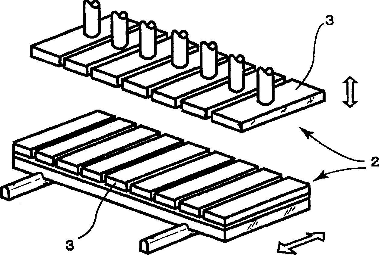
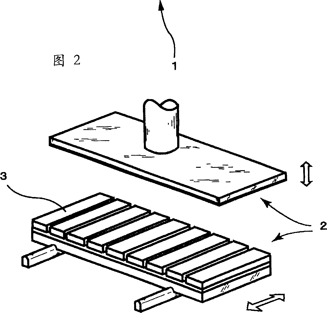
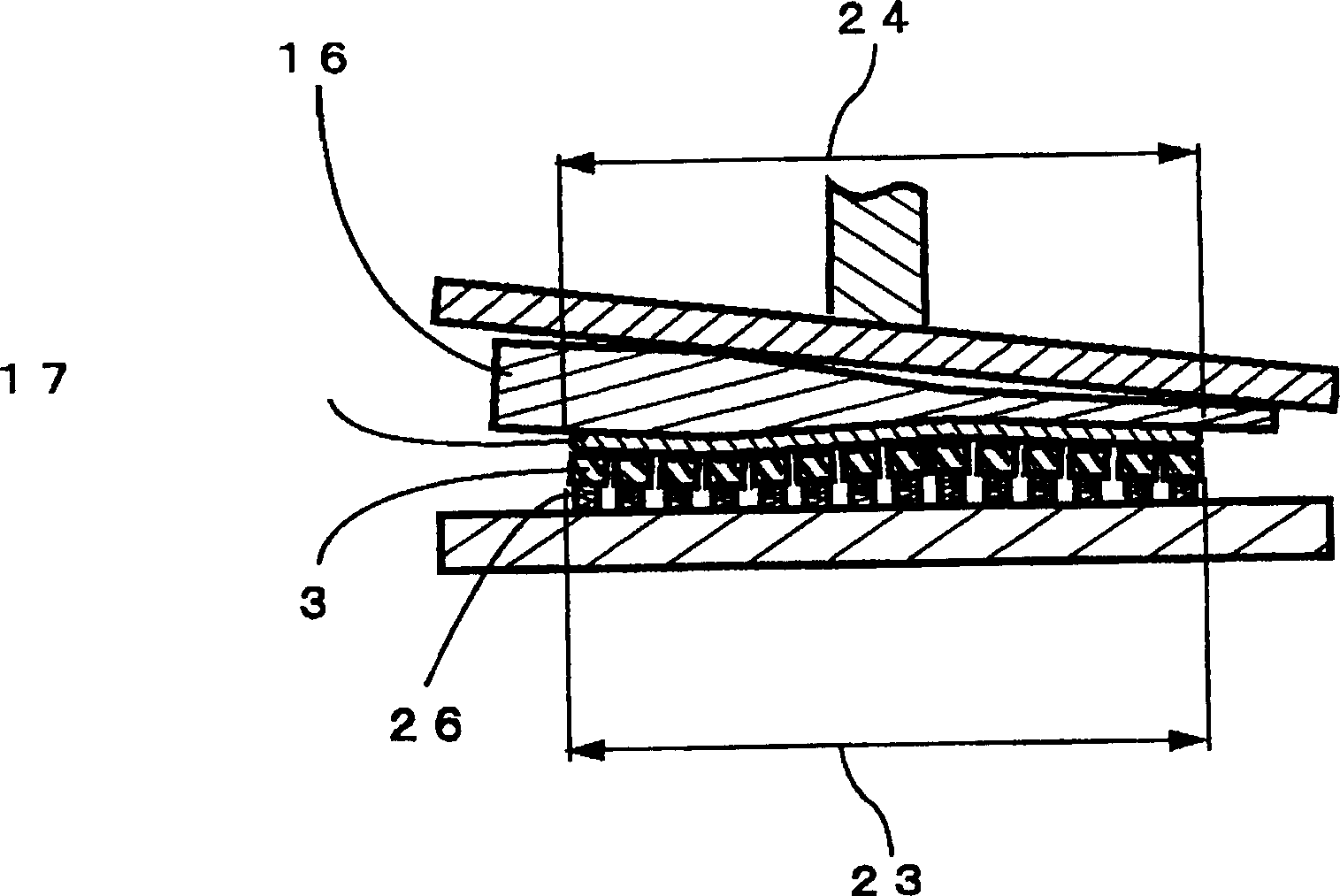
[0094] In this example, if Figure 5 with Image 6 As shown, the upper pressing plate 31 is formed in an overall flat plate shape, and the lower pressing plate 32 is composed of a plurality of pressing plate members 33 . Moreover, each pressing plate member 33 is formed into a rectangular prism rod shape, and the coil spring 45 is in contact with the lower portion of both ends of the pressing plate member 33, and the pressing plate member 33 contacted by the coil spring 45 is placed on the work table 41 which moves in the horizontal direction. , having a structure arranged continuously along a direction perpendicular to the rolling direction of the mandrel.

[0095] Specifically, female threaded holes 37 are provided at the lower parts of both ends of the bar-shaped pressing plate member 33 forming a quadrangular prism, and the cylindrical rod-shap...


PUM


Abstract

Provided is a manufacturing apparatus and method of a golf club shaft having a mandrel on which pre-preg can tightly be wound though the outer surface of the mandrel varies complicatedly and capable of obtaining the shaft with stabilized quality. The manufacturing apparatus 1 of the golf club shaft has a pair of upper and lower pressing plates 2 arranged so that their pressurizing surfaces face each other, the pre-preg for molding the golf shaft and the mandrel are inserted and held between the pressing plates 2, and the mandrel is rotated to wind the pre-preg onto the mandrel. The pressing plates 2 are formed of a plurality of pressing plate members 3.

Description

technical field [0001] The present invention relates to a manufacturing device and a manufacturing method for manufacturing a golf club shaft. Background technique [0002] In order to manufacture a fiber-reinforced resin golf club shaft, a mandrel having an arbitrary taper is prepared, a laminated material forming the golf club shaft is laminated on the mandrel, and heated After hardening, the mandrel is pulled out to obtain the required golf club shaft. [0003] Here, in the process of laminating the laminated material on the mandrel, various lamination methods such as a sheet pressing method, a long fiber winding method, a triaxial plating method, and the like may be employed. [0004] In the sheet press method among the lamination methods, the laminate is laminated by winding a laminate sheet made of resin-impregnated reinforcing fibers around the outer periphery of a mandrel in layers. [0005] Traditional techniques such as Figure 8 As shown, the manufacturing devic...

Claims


Application Information

Patent Timeline
Patent Type & Authority Applications(China)
IPC IPC(8): A63B53/10A63B102/32B29C63/04
Inventor 松井泰志木村辉之山口丰
Owner MIZUNO CORPORATION
Why Eureka
Try Eureka