No-overlapping sample pulse signal generator and pulse signal producing method

A signal generator and pulse signal technology, applied in image communication, television, electrical components, etc., can solve problems such as image distortion

Inactive Publication Date: 2003-03-19
TPO DISPLAY
View PDF0 Cites 4 Cited by
  • Summary
  • Abstract
  • Description
  • Claims
  • Application Information

AI Technical Summary

Problems solved by technology

[0004] The purpose of the present invention is to provide a non-overlapped sampling pulse signal generator to solve the image distortion caused by signal overlap in common thin film transistor liquid crystal displays

Method used


Image

  • No-overlapping sample pulse signal generator and pulse signal producing method
  • No-overlapping sample pulse signal generator and pulse signal producing method
  • No-overlapping sample pulse signal generator and pulse signal producing method

Examples


Embodiment Construction

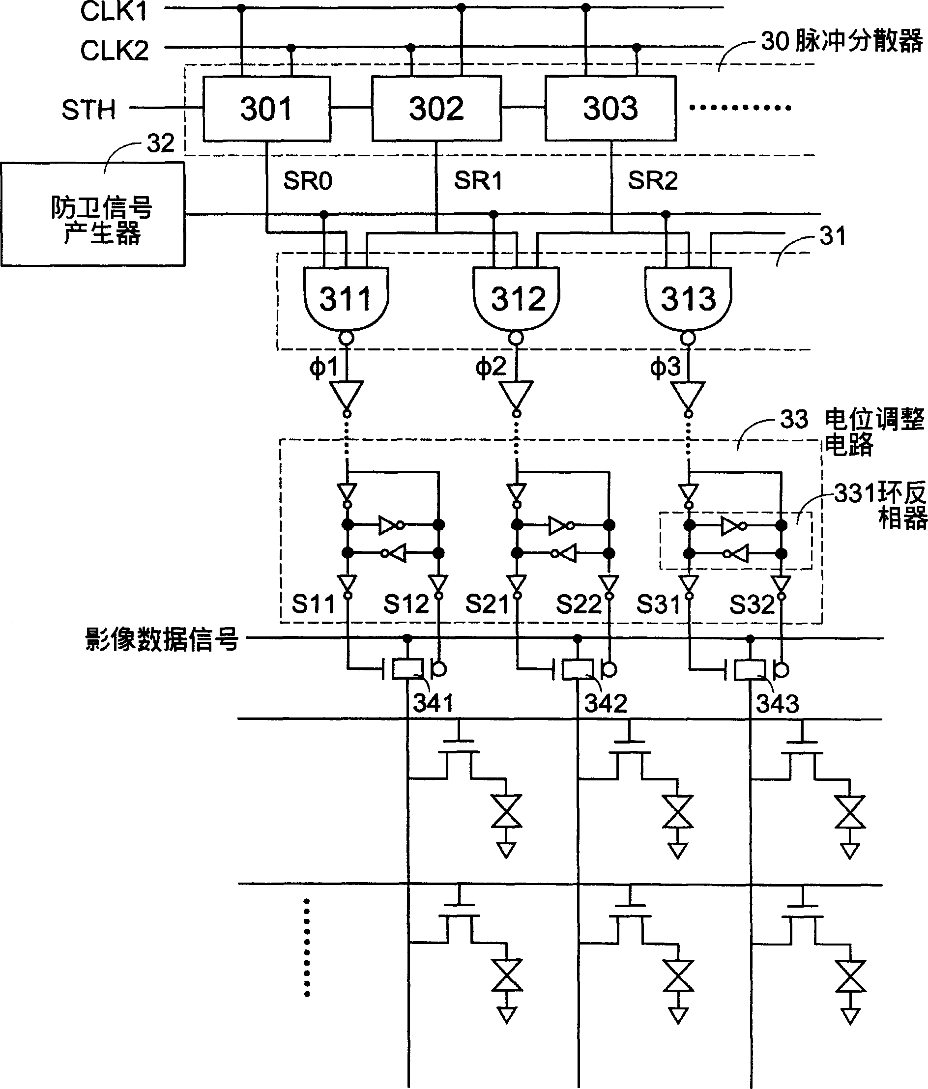
[0021] See image 3 , which is a schematic diagram of a preferred embodiment of the non-overlapping sampling pulse signal generator of the present invention, wherein the pulse disperser 30 is formed by connecting several shift registers 301, 302, 303..., etc. in this embodiment, It mainly responds to the triggering of a start pulse STH and the control of a pair of complementary clock signals CLK1, CLK2 to sequentially generate several pulse signals with different phases, and respectively use the corresponding output terminals SR0, SR1, SR2...etc. For output, please refer to the schematic diagram of the waveform shown in Figure 4(a) for its related waveforms, because when the high potential region of the start pulse STH includes more than one change edge of the clock signal CLK1 (or CLK2), the generated pulse The high potentials of the signals SR0, SR1, SR2, . . . will produce overlap. In this embodiment, since the high potential region of the start pulse STH covers the two ch...


PUM


Abstract

The present invention relates to to a signal generator of free overlap sampling impulse can be used on the active matrix display, which includes an impulse scatterer, a defense, signal generator and a logical operation circuit. The method to generate the signal includes the following steps, the impulse scatterer to respond to a trigger of a starting impulse to generate several impulse signals in different phase and then to export them separately, the defense signal generated to provide a defence signal which switches between the first electric potential and the second electric potential, the logic operation circuit to receive these impulse signals to carry out an operation with the defense signal for exporting several numbers of sampling signal in sequence, the adjacent two sampling sections of sampling signals having a time interval for avoiding the overlap according to the time of the defense signal at the second electric potential.

Description

technical field [0001] The invention relates to a non-overlapping sampling pulse signal generator and a generating method, especially a non-overlapping sampling pulse signal generator and a generating method applied to an active matrix display. Background technique [0002] See figure 1 , which is a schematic circuit block diagram of a commonly used thin film transistor liquid crystal display, wherein a horizontal scanning circuit (horizontal scanning circuit) 10 is used to sequentially generate several sampling pulses (sampling pulse) Φ1, Φ2, ..., Φn (in the figure not shown) to control the switch circuits S1, S2, ... Sn (not shown in the figure) on or off, to selectively transmit the image data signal SIG to the data lines Y1, Y2, ..., Yn (not shown in the figure out), and then achieve the purpose of updating the image data. [0003] see you again figure 2 , which is a schematic diagram of the waveforms of the above-mentioned sampling pulses Φ1 and Φ2. Ideally, the ris...

Claims


Application Information

Patent Timeline
IPC IPC(8): H04N3/14
Inventor 曾戎骏王玮
Owner TPO DISPLAY
Why Eureka
Try Eureka