
Distributed optical fibre temperature sensor system

A technology of temperature sensors and distributed optical fibers, applied in thermometers, thermometers with physical/chemical changes, instruments, etc., can solve the problems of inability to locate, monitor and measure the temperature of multiple points at the same time, and cannot operate normally, so as to improve Efficiency, high safety, and wide application range

Inactive Publication Date: 2003-03-05
CHINA JILIANG UNIV
View PDF0 Cites 34 Cited by
  • Summary
  • Abstract
  • Description
  • Claims
  • Application Information

AI Technical Summary

Problems solved by technology

Although these instruments can accurately measure the temperature value of a certain point, they cannot monitor and measure the temperature of multiple points at the same time and cannot be positioned; in dangerous and harmful environments, some temperature measuring instruments cannot operate normally due to their own unsafe factors

Method used


Image

  • Distributed optical fibre temperature sensor system
  • Distributed optical fibre temperature sensor system
  • Distributed optical fibre temperature sensor system

Examples


Embodiment Construction

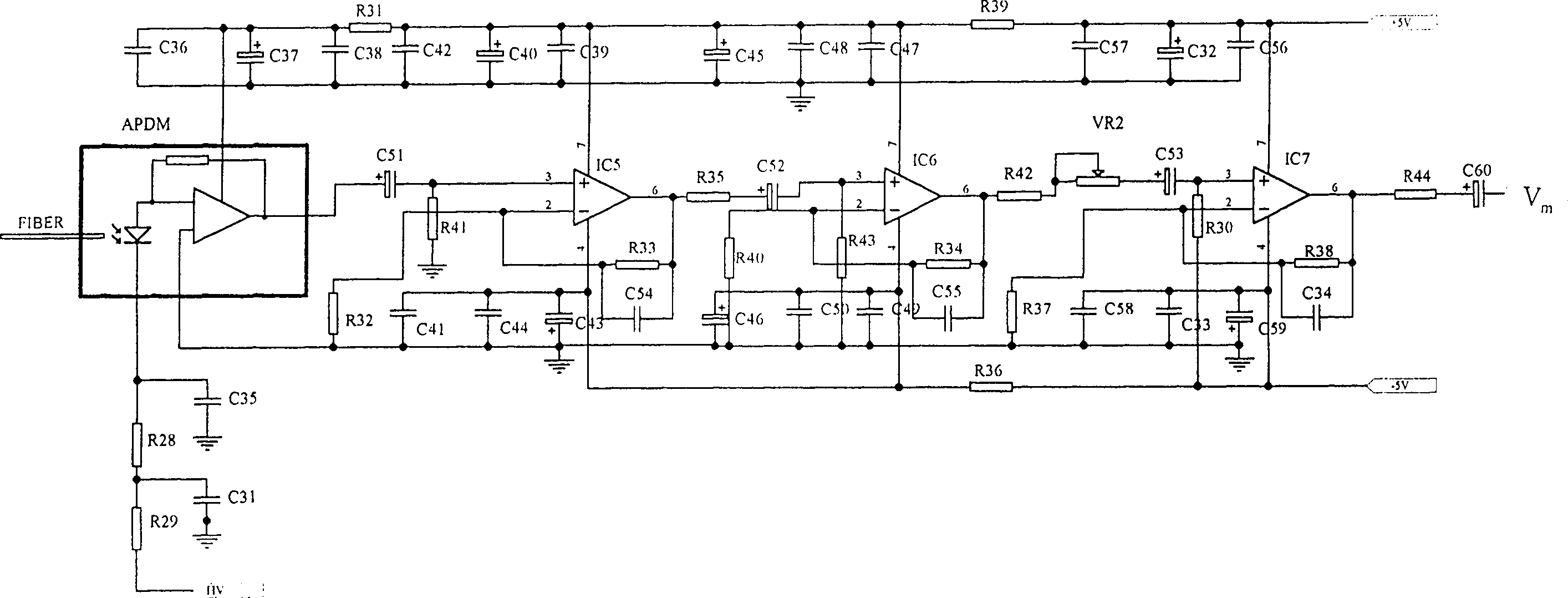
[0017] figure 2 The laser generator shown includes a pulse generator composed of 555 timer IC1, resistors R1, R2, R3, diodes D3, D4, and capacitor C1, which generates pulse waves with a frequency of about 1KHz as the driving signal source for the transmitting part. The driving circuit composed of resistors R4, R5, R6, transistor TR1, and capacitor C7 is used to increase the driving capability of the pulse signal and accelerate the rising speed of the signal pulse. A shaping and differential circuit composed of diode D1, resistors R7, R8, R9, and capacitor C2. Laser emitting circuit composed of transistors TR2, TR3, diode D2, resistors R11, R12, R13, capacitor C3, and laser module LDM.

[0018] When the driving pulse is at a low level, the transistors TR2 and TR3 are turned off, and the high-voltage source charges the capacitor C3 through the loop composed of the resistor R13, the capacitor C3 and the diode D2 through the HV terminal. When the driving pulse is at a high leve...


PUM


Abstract

The distributed optical fiber temperature sensor is a kind of temperature-measuring equipment. It includes laser generator, optical fiber with bidirectional coupler, light wave-division multiplexer (WDM), two light avalanche transistor, two amplifiers, signal-sampling cara and computer. The generated laser pulse enters the fiber-optical to output back dispersion light whose echo channel has two paths; one path as Raman back dispersion light separated by the light WDM enters one avalanche transistor and the other path as Rayleigh back dispersion light enters the other end. Two avalanche transistor make the photoelectric conversion, and the output signals apart enter the amplifier whose output end linked with the input end of the signal-sampling card whose output end linked with the computer.

Description

technical field [0001] The invention relates to a device for measuring temperature by using optical fiber backscattered light. Background technique [0002] At present, the instruments used to measure temperature mainly include thermometers, thermocouples, thermal resistance and infrared thermometers. Although these instruments can accurately measure the temperature value of a certain point, they cannot monitor and measure the temperature of multiple points at the same time and cannot be positioned; in dangerous and harmful environments, some temperature measuring instruments cannot operate normally due to their own unsafe factors. Contents of the invention [0003] The invention aims to provide a distributed optical fiber temperature sensor system with wide application range and the ability to simultaneously measure multi-point temperatures. [0004] The distributed optical fiber temperature sensor system uses the temperatur...

Claims


Application Information

Patent Timeline
Patent Type & Authority Applications(China)
IPC IPC(8): G01J5/54G01K11/32
Inventor 张在宣郭宁余向东吴孝彪
Owner CHINA JILIANG UNIV
Learn More