Direct liquid level controlling system with single-loop pump
A variable frequency water pump, level control technology, applied in liquid level control, control/regulation system, non-electric variable control and other directions, can solve problems such as increasing project cost and operating cost
- Summary
- Abstract
- Description
- Claims
- Application Information
AI Technical Summary
Problems solved by technology
Method used
Image

Examples
Embodiment 1
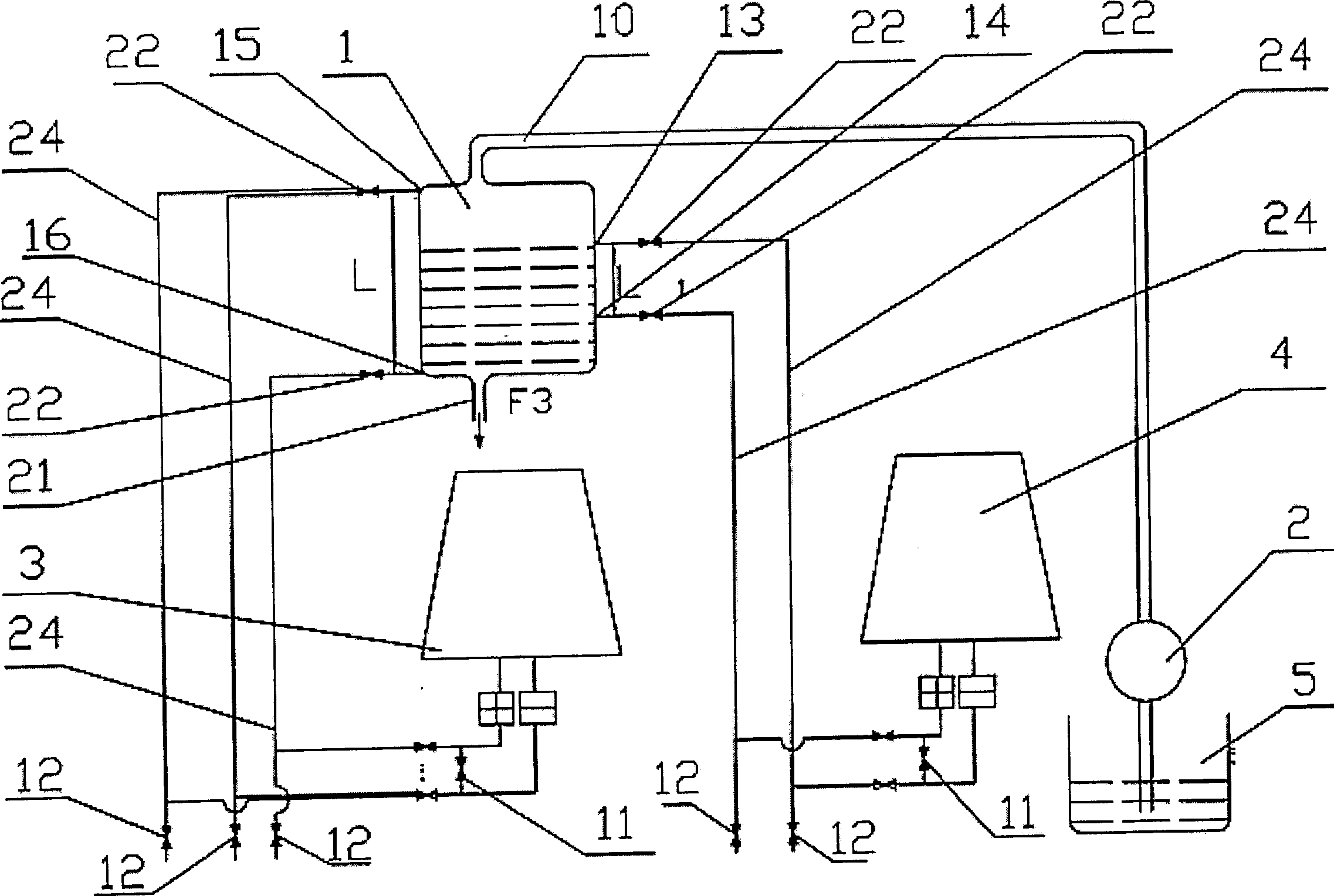
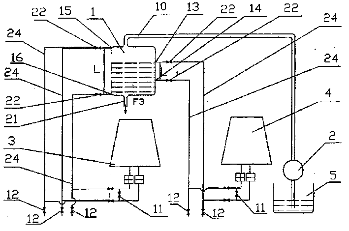
[0031] One end of the water inlet pipe (10) is connected with the water outlet of the water pump (2), the other end of the water inlet pipe (10) is connected with the airtight container (1), and the water inlet of the water pump (2) is connected with the water storage tank ( 5) connected with each other, the lower end of the airtight container (1) is provided with an output water pipeline (21), and the output water pipeline (21) is connected with the user.
[0032] Take the total length of the airtight container (1) as the container liquid level height (L), the upper part of one side of the airtight container (1) is provided with a container liquid level upper limit display detection point (15), and the container liquid level upper limit display detection point (15) One end is connected to the upper part of one side of the airtight container (1), and the other end of the container liquid level upper limit display detection point (15) is connected to one end of the needle valve ...
Embodiment 2
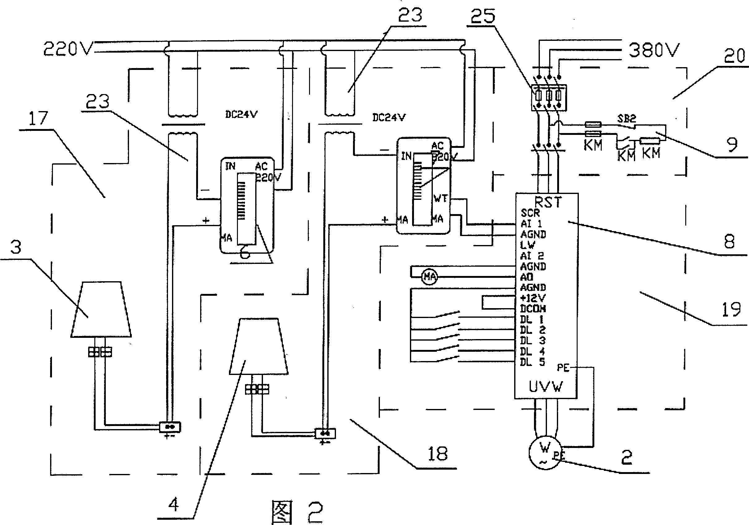
[0039] One end of the container differential pressure transmitter (3) of the container liquid level detection circuit (17) is connected to the MA end of the barometer (6), and the other end of the container differential pressure transmitter (3) is connected to the container liquid level detection circuit The positive end of the 24V power supply (23) of (17) is connected, and the negative end of the 24V point source (23) of the container liquid level detection circuit (17) is connected with the bar display instrument (6) IN of the container liquid level detection circuit (17). end connected.
[0040] One end of the control liquid level differential pressure transmitter (4) of the control liquid level detection circuit (18) is connected to the MA end of the digital regulator (7), and the control liquid level differential pressure transmitter of the control liquid level detection circuit (18) The other end of the regulator (4) is connected with one end of the 24V power supply (23...
Embodiment 3
[0044] During use, start the opening and closing switch (9) of the opening and closing circuit (20), the container liquid level upper limit display detection point (15) and the container liquid level lower limit display detection point (16) of the container liquid level circuit on the side of the airtight container (1) ) The liquid level situation in the closed container (1) is transmitted to the container liquid level through the pipeline (24) of the upper limit display detection point (15) of the container liquid level and the pipeline (24) of the lower limit display detection point (16) of the container liquid level The container liquid level differential pressure transmitter (3) of the detection circuit (17), the container liquid level differential pressure transmitter (3) converts the pressure signal into a liquid level signal and transmits it to the light column display of the container liquid level detection circuit (17) instrument (6), the light beam display instrument ...
PUM
 Abstract
Description
Claims
Application Information
 - R&D
- Intellectual Property
- Life Sciences
- Materials
- Tech Scout
- Unparalleled Data Quality
- Higher Quality Content
- 60% Fewer Hallucinations
Browse by: Latest US Patents, China's latest patents, Technical Efficacy Thesaurus, Application Domain, Technology Topic, Popular Technical Reports.
© 2025 PatSnap. All rights reserved.Legal|Privacy policy|Modern Slavery Act Transparency Statement|Sitemap|About US| Contact US: help@patsnap.com