


Quick Research
Generate reliable direction feasibility study reports for your R&D in just a few steps.

Technical Q&A
Discover and master advanced knowledge NOW. Basics, ideas, possibilities, all at once.

Find Solutions
As an expert in R&D theories, this can generate solutions to your technical problems instantly.

Evaluate Feasibility
Analyze your overall solution with one click, know your potential R&D risks in advance.

Monitor Landscape
Get weekly tech updates, stay abreast of the latest tech innovations and key insights.
Liquid crystal display
A liquid crystal display, liquid crystal technology, applied in instruments, polarizing elements, optics, etc., can solve problems such as difficulty in improving the brightness of liquid crystal display units
- Summary
- Abstract
- Description
- Claims
- Application Information
AI Technical Summary
Problems solved by technology
Method used
Image

Examples
Embodiment Construction
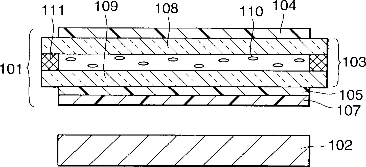
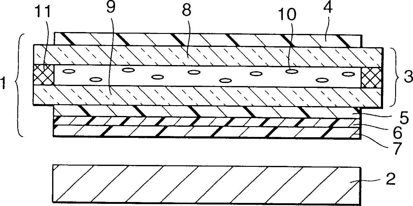
[0019] Refer below Figure 2A , 2B and 2C describe a liquid crystal display in one embodiment of the invention.
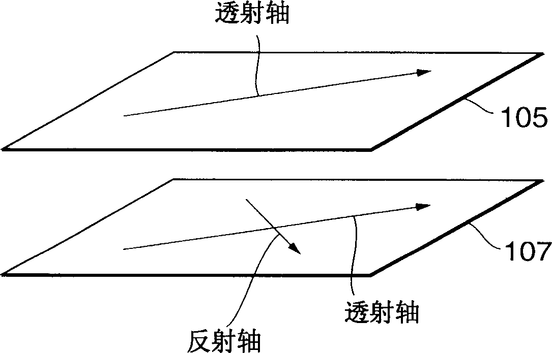
[0020] Figure 2A It is a sectional view in the case of cutting the liquid crystal display of the present invention on one plane perpendicular to the substrate. Figure 2B Schematic illustration of the relationship between the polarization axes of two polarizers mounted on one side of the substrate and a light-emitting unit on the side of the liquid crystal display. Figure 2C Schematically illustrate the structure of the light emitting unit. This liquid crystal display includes a liquid crystal display unit 1 and a light emitting unit 2, which are structured as follows. Note that hereafter, the side of the liquid crystal display unit 1 on which the light-emitting unit 2 is installed is called the back, and the side of the liquid crystal display unit 1 opposite to the back is called the front.
[0021] First, if Figure 2A As shown, polarizers 4 and 5 are pla...
PUM
 Abstract
Description
Claims
Application Information
 - R&D Engineer
- R&D Manager
- IP Professional
- Industry Leading Data Capabilities
- Powerful AI technology
- Patent DNA Extraction
Browse by: Latest US Patents, China's latest patents, Technical Efficacy Thesaurus, Application Domain, Technology Topic, Popular Technical Reports.
© 2024 PatSnap. All rights reserved.Legal|Privacy policy|Modern Slavery Act Transparency Statement|Sitemap|About US| Contact US: help@patsnap.com