Radio receiver and radio receiving method
A wireless receiving device and wireless receiving technology, applied in the directions of radio transmission system, diversity/multi-antenna system, space transmit diversity, etc., can solve the problems of inability to obtain diversity gain, inability to improve reception characteristics, etc.
- Summary
- Abstract
- Description
- Claims
- Application Information
AI Technical Summary
Problems solved by technology
Method used
Image

Examples
Embodiment 1
[0036] The wireless receiving apparatus according to Embodiment 1 of the present invention separates the received pilot channel signal into each antenna and performs in-phase addition.
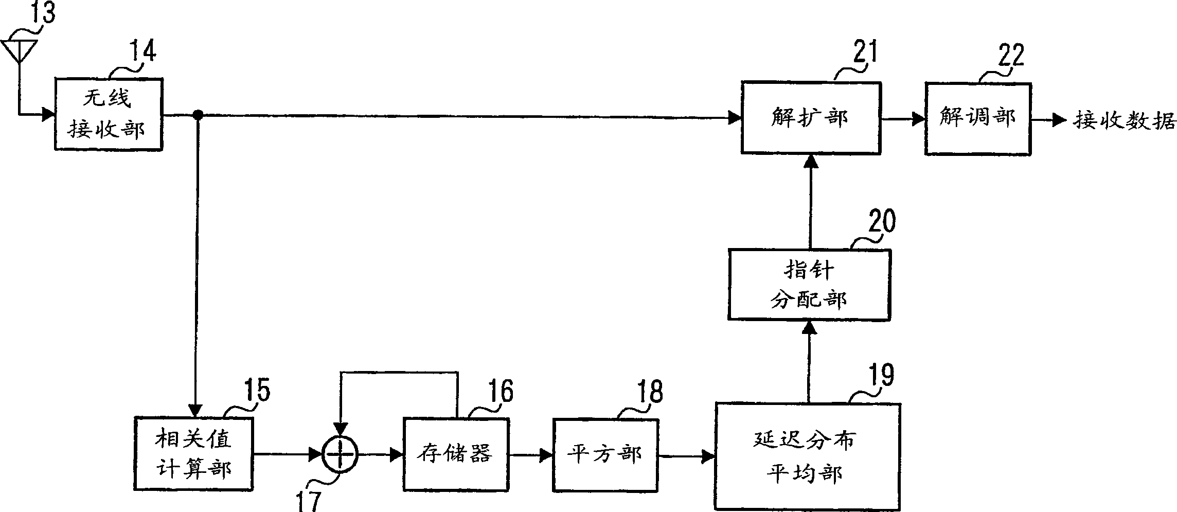
[0037] Figure 4 It is a block diagram of main parts showing a schematic configuration of the radio receiving apparatus according to Embodiment 1 of the present invention. exist Figure 4 Among them, the radio receiving unit 102 performs predetermined radio processing (down-conversion, A / D conversion, etc.) on the signal received via the antenna 101 . The correlation value calculation unit 103 performs despreading processing on the pilot channel signal. The switching control unit 105 performs switching control of the switch 104 .
[0038] Delay unit 106 delays the pilot channel signal by 1 symbol time. Adder 107 adds the pilot channel signal delayed by 1 symbol time to the pilot channel signal. Subtractor 108 subtracts the pilot channel signal delayed by one symbol time from the pilot cha...
Embodiment 2
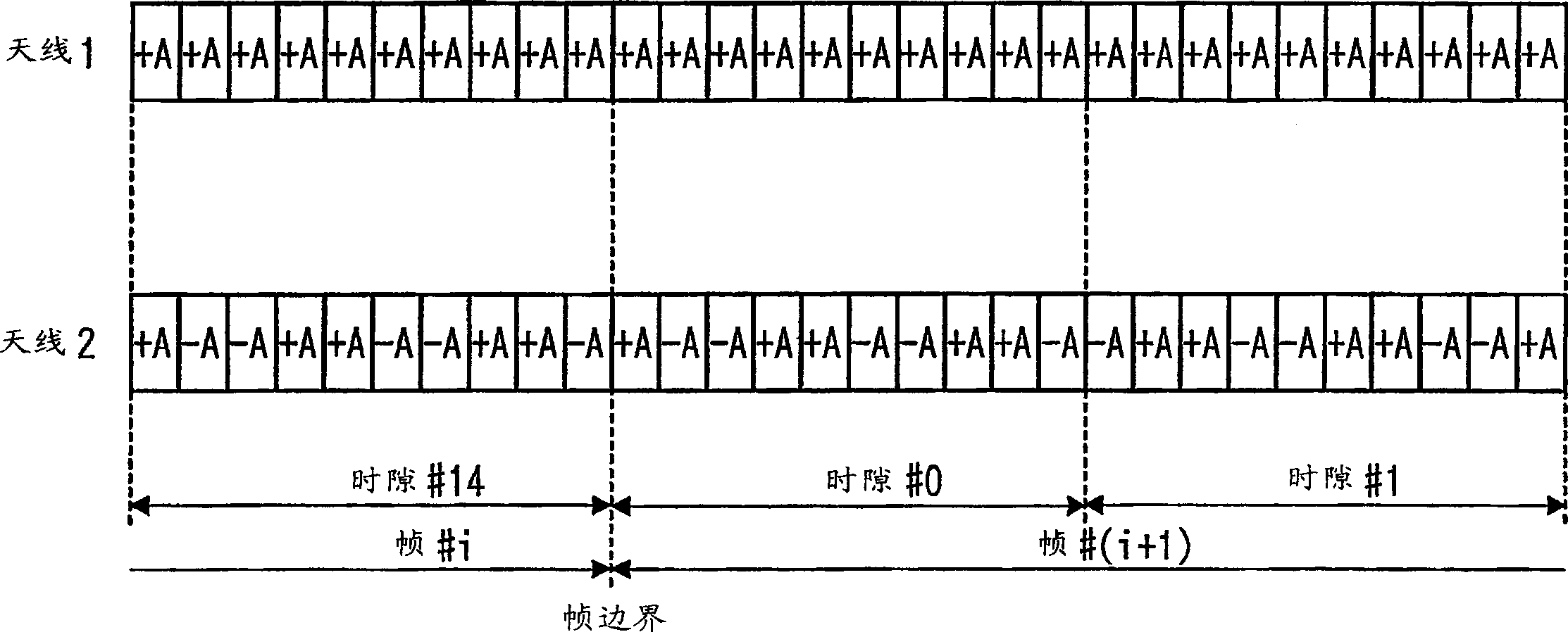
[0067] The wireless receiving device of Embodiment 2 of the present invention is to transmit the correlation value D corresponding to +A sent from the antenna 2 plus Between the in-phase addition, the correlation value D corresponding to -A sent from antenna 2 minus Between the same phase addition.
[0068] Figure 6 It is a block diagram of main parts showing a schematic configuration of a wireless receiving apparatus according to Embodiment 2 of the present invention. In addition, the same reference numerals are assigned to the same structures as in the first embodiment, and detailed descriptions thereof are omitted.
[0069] exist Figure 6 Among them, the switching control unit 201 performs switching control of the switch 202 and the switch 203 . Memory 204 and Adder 206 enable D plus Between the same phase addition. On the other hand, memory 205 and adder 206 make D minus Between the same phase addition. The square addition part 207 will be D plus and D minus Sq...
Embodiment 3
[0079] The wireless receiving device of Embodiment 3 of the present invention switches the correlation value D corresponding to +A transmitted from the antenna 2 at each specified unit (for example, each time slot). plus Between the in-phase addition and the correlation value D corresponding to -A sent from antenna 2 minus In-phase addition between.
[0080] Figure 7 It is a block diagram of main parts showing a schematic configuration of a wireless receiving apparatus according to Embodiment 3 of the present invention. In addition, the same reference numerals are assigned to the same structures as in the first embodiment, and detailed description thereof will be omitted.
[0081] exist Figure 7 Among them, the reception symbol control unit 301 controls the radio reception unit 102 so that only designated pilot symbols are received. That is, the radio receiving unit 102 only performs an operation of receiving a designated pilot symbol.
[0082] The correlation value cal...
PUM
 Abstract
Description
Claims
Application Information
 - R&D
- Intellectual Property
- Life Sciences
- Materials
- Tech Scout
- Unparalleled Data Quality
- Higher Quality Content
- 60% Fewer Hallucinations
Browse by: Latest US Patents, China's latest patents, Technical Efficacy Thesaurus, Application Domain, Technology Topic, Popular Technical Reports.
© 2025 PatSnap. All rights reserved.Legal|Privacy policy|Modern Slavery Act Transparency Statement|Sitemap|About US| Contact US: help@patsnap.com