
Static force loading measuring and controlling equipment for material microstructure tester and its method

A microstructure, static load technology, applied in the direction of measuring devices, analyzing materials, using optical devices, etc., can solve the problems of fine observation and precise measurement, difficulty, poor observation effect, etc., to achieve high-precision adjustment, convenient and fast The effect of convenient positioning and operation

Inactive Publication Date: 2002-11-20
TIANJIN UNIV
View PDF0 Cites 11 Cited by
  • Summary
  • Abstract
  • Description
  • Claims
  • Application Information

AI Technical Summary

Problems solved by technology

However, currently known instruments and control methods for measuring microstatic force of materials, on the one hand, use conventional microscopes, and stick test paper on the surface of the test piece for observation and measurement, but the observation effect is poor and the measurement accuracy is low. , cannot meet the needs of fine observation and precise measurement of the above materials
On the other hand, advanced, expensive, and various operating methods of electron microscopes are used, but due to the lack of measurement methods, it is also impossible to perform subtle observations and precise measurements on the microstructure of new functional materials, nanomaterials, and material mechanics. Materials, research and manufacture of new equipment have brought a lot of inconvenience and difficulties

Method used


Image

  • Static force loading measuring and controlling equipment for material microstructure tester and its method
  • Static force loading measuring and controlling equipment for material microstructure tester and its method
  • Static force loading measuring and controlling equipment for material microstructure tester and its method

Examples


Embodiment Construction

[0024] Below in conjunction with accompanying drawing, the implementation of the present invention is described in detail as follows:

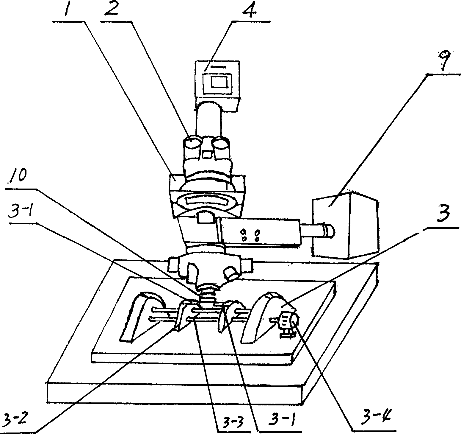
[0025] exist figure 1 Among them, a static loading device 3 is provided on the stage of the microscope 1 . The microscope 1 can adopt microscopic objective lenses with different magnifications, such as: OLYMPUS industrial microscope, the minimum magnification is 50 times, the maximum magnification is 2000 times, and it is equipped with a long focal length objective lens. The microscope 1 can also adopt a polarizing microscope, and its magnification can be selected according to the different microstructures of the test pieces. The microscope 1 is provided with a light source device 9, which has wires connected to the power supply 6 for observing and measuring the light source. There is a space of 160-200mm between the stage of the microscope 1 and the microscope objective lens, which is used to place large materials, components, and loading e...


PUM


Abstract

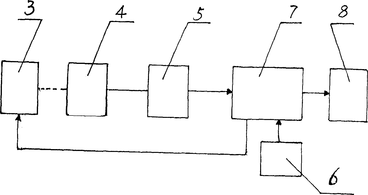
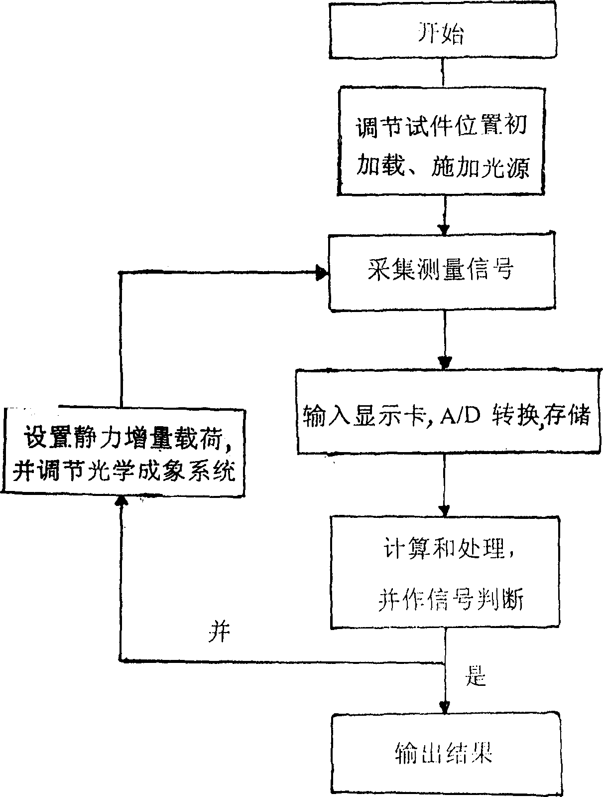
A static loading device is placed on the microscope, a signal-collecting device is placed at the place of microscope oculr, said signal-collecting device is connected with image-collecting card, microprocessor and display in turn by means of conductive wire, said microprocessor is respectively connected with power supply and static loading device by means of conducting wire, its light source device is connected with power supply by means of conducting wire. Its control method includes the following steps: 1. starting; 2. regulating position of test piece, primary loading and applying light source; 3. collecting measuring signal, inputting said signal into image-collecting card and making A / D conversion and storage; and 4. calculating and processing measured data signal inputted by image collecting card by using microprocessor and making signal judgement.

Description

technical field [0001] The invention belongs to the category of instrument measurement, and in particular relates to a device and a control method for material microstatic force measurement. Background technique [0002] At present, for the development of new functional materials, nanomaterials, microelectronic devices, micromachines, and material mechanics, there is an urgent need for simple, reliable, non-contact testing, and testing functions such as displacement, deformation, stress, and rotation angle. Apparatus and methods. However, currently known instruments and control methods for measuring microstatic force of materials, on the one hand, use conventional microscopes, and stick test paper on the surface of the test piece for observation and measurement, but the observation effect is poor and the measurement accuracy is low. , cannot satisfy the subtle observation and precise measurement of the above materials. On the other hand, adva...

Claims


Application Information

Patent Timeline
IPC IPC(8): G01B9/04G01B11/00G01N3/08
Inventor 李鸿琦邢冬梅佟景伟马世虎李林安王世斌
Owner TIANJIN UNIV
Learn More