
Patsnap Eureka
For R&D, Patsnap Eureka makes reading and utilizing patents & technical documents easy.
Patsnap Eureka AIR
Designed for self-driven R&D workflows. Generate viable solutions, solve complex R&D challenges, empower your innovation with AI.

Patsnap Eureka Materials
Designed for material experts only. Revolutionize your material R&D, from search, analyze, to developing new materials.

TechResearch
Generate reliable direction feasibility study reports for your R&D in just a few steps.

TechSeek
Discover and master advanced knowledge NOW. Basics, ideas, possibilities, all at once.

TechMind
As an expert in R&D Theories, TechMind can generates customized viable solutions instantly.

TechRisk
Analyze your overall solution with one click, know your potential R&D risks in advance.

TechMonitor
Get weekly tech updates, stay abreast of the latest tech innovations and key insights.
Column-shape locking mechanism
A locking mechanism, cylindrical technology, applied in the field of cylindrical locking mechanism, can solve the problems of unguaranteed unlocking and locking, and achieve high anti-theft effect and obvious advantages
- Summary
- Abstract
- Description
- Claims
- Application Information
AI Technical Summary
Problems solved by technology
Method used
Image


Examples
Embodiment Construction
[0026] Embodiments of the present invention will be described below with reference to the drawings.
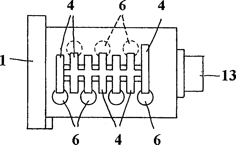
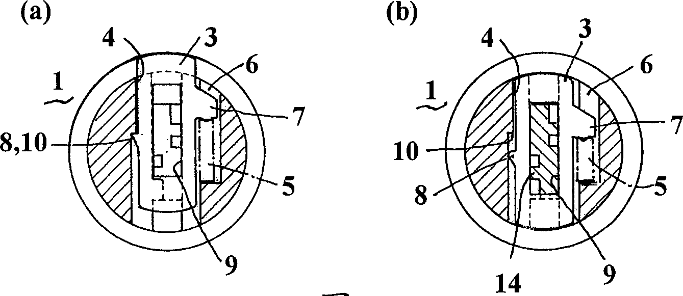
[0027] figure 1 is an exploded perspective view of an embodiment of the present invention. figure 2 It is the plane view of the cylindrical lock body. image 3 (a) is a transverse sectional view showing the locked state of the steering piece and the coil spring inserted from one side of the cylindrical lock body. image 3 (b) is a transverse sectional view of the same cylindrical lock body in the open state. Figure 4 (a) is a transverse sectional view showing a locking state of a steering piece and a coil spring inserted from opposite sides of a cylindrical lock body. and Figure 4 (b) is also a transverse cross-sectional view showing the same cylindrical lock body in an open state.
[0028] In the accompanying drawings, reference numeral 1 represents a cylindrical lock body, one end along its axial direction is provided with a key hole 2, as shown in the figure, two si...
PUM
 Abstract
Description
Claims
Application Information
 - R&D Engineer
- R&D Manager
- IP Professional
- Industry Leading Data Capabilities
- Powerful AI technology
- Patent DNA Extraction
Browse by: Latest US Patents, China's latest patents, Technical Efficacy Thesaurus, Application Domain, Technology Topic, Popular Technical Reports.
© 2024 PatSnap. All rights reserved.Legal|Privacy policy|Modern Slavery Act Transparency Statement|Sitemap|About US| Contact US: help@patsnap.com