Power supply circuit

A technology of power supply circuit and power supply voltage, applied in circuit devices, DC network circuit devices, electrical components, etc., can solve the problems of large power consumption and large influence, and achieve the purpose of reducing power consumption, low power consumption, and restraining battery consumption. Effect

Inactive Publication Date: 2002-09-25
RICOH KK
View PDF0 Cites 10 Cited by
  • Summary
  • Abstract
  • Description
  • Claims
  • Application Information

AI Technical Summary

Problems solved by technology

When the DC-DC converter 110 is used in the always active state, the power consumption of the DC-DC converter 110 itself has a great influence on the power consumption of the device
In addition, in a device that uses a battery as a power source, it is necessary to reduce power consumption as much as possible to suppress battery consumption. If the DC-DC transformer 110 is replaced with a voltage regulator that consumes a lot of power, there is a problem of large power consumption.

Method used


Image

  • Power supply circuit
  • Power supply circuit
  • Power supply circuit

Examples


no. 1 example

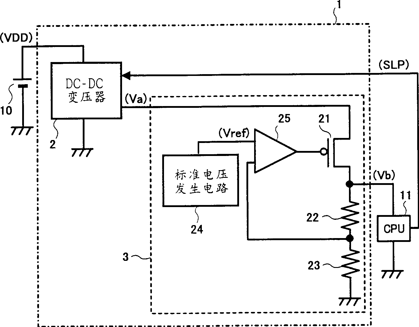
[0071] figure 1 This is an example of the configuration of the power supply circuit of the first embodiment of the present invention.

[0072] exist figure 1 Among them, the power supply circuit 1 is composed of a DC-DC transformer 2 and a voltage regulator 3, and the power supply voltage VDD is applied from a DC power supply 10 such as various batteries (including secondary batteries), and the DC-DC transformer 2 steps down the above-mentioned power supply voltage VDD. , to output a predetermined voltage Va, and the voltage regulator 3 steps down the output voltage from the DC-DC transformer 2 to output a predetermined voltage Vb.

[0073] The DC-DC transformer 2 is connected between the power terminal to which the power supply voltage VDD is applied and the ground, the voltage regulator 3 is connected between the output terminal of the DC-DC transformer 2 and the ground, and the output terminal of the voltage regulator 3 is connected to the power supply target. The power...

no. 2 example

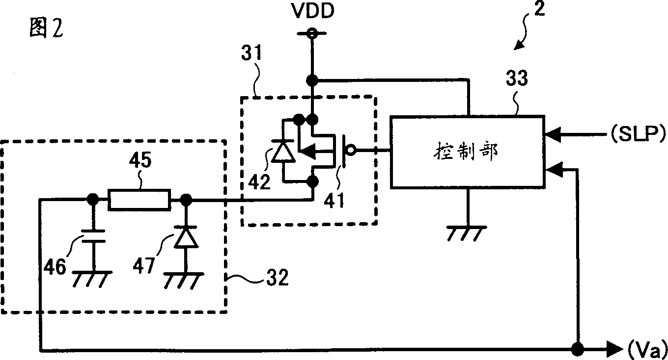
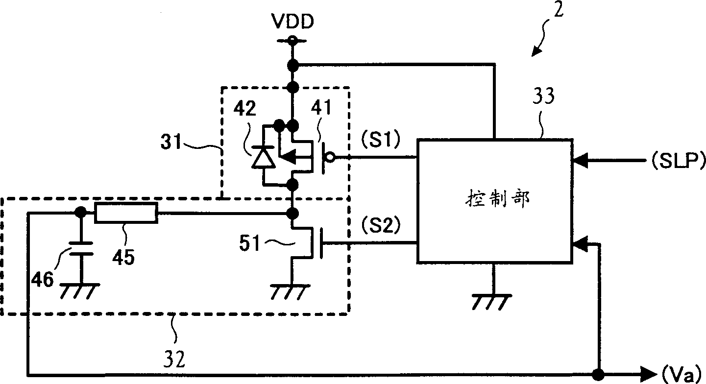
[0092] In the first embodiment described above, when the standby state is reached, the DC-DC transformer 2 becomes inactive, stops its operation, and outputs to the voltage regulator 3 through the power supply voltage VDD. However, if this is the case, when the standby mode is shifted to the normal operation, the output voltage of the DC-DC transformer 2 may generate a negative pulse signal, and at the same time, when the normal operation is shifted to the standby mode, the output voltage of the DC-DC transformer 2 may be negative. Overshoot may occur. Therefore, it is preferable to add a function of preventing the above-mentioned negative pulse signal and overshoot to the DC-DC transformer, which is the second embodiment of the present invention.

[0093] In the diagram of the configuration example of the power supply circuit in the second embodiment of the present invention, except that the DC-DC transformer 2 is changed to a DC-DC transformer 2a, and the power supply circui...


PUM


Abstract

The present invention relates to a power supply circuit used in devices using various batteries such as mobile phones, and more particularly to a power supply circuit capable of reducing power consumption. When the CPU 11 is in normal operation, the DC-DC transformer 2 is used to efficiently step down the power supply voltage VDD to the voltage Va, and then the voltage regulator 3 is used to step down to obtain a stable voltage Vb, which is supplied to the CPU 11; if the CPU 11 is in a standby state, the DC - The DC transformer 2 becomes inactive, stops its operation, and suppresses power consumption. At the same time, only the voltage regulator 3 adjusts the power supply voltage VDD passed through the DC-DC transformer 2 to a desired voltage Vb, and supplies it to the CPU 11 . The power supply circuit of the present invention can reduce power consumption in a standby state, and at the same time, even when a device to be supplied with power is intermittently operated in the standby state, power can be supplied to the device.

Description

technical field [0001] The present invention relates to a power supply circuit used in devices using various types of batteries, such as mobile phones, and more particularly to a power supply circuit capable of realizing low power consumption. Background technique [0002] Conventionally, a voltage regulator and a DC-DC transformer have been used as a power supply circuit for stepping down a DC voltage supplied from a DC power supply to a predetermined voltage. [0003] Figure 14 It is a circuit diagram of a known technical example of a power supply circuit using a voltage regulator. exist Figure 14 In the voltage regulator 100, P-channel type MOS transistors (hereinafter abbreviated as "PMOS transistors") are connected in series between the power supply terminal to which the power supply voltage VDD is applied from a DC power supply 101 such as various batteries (including secondary batteries) and the ground. ) 102, resistors 103 and 104. [0004...

Claims


Application Information

Patent Timeline
Patent Type & Authority Applications(China)
IPC IPC(8): H02J1/00G05F1/56G05F1/565G05F1/59H02M3/155H02M3/156
CPCG05F1/565H02M3/156H02M1/0045
Inventor 松尾正浩新田升一
Owner RICOH KK
Why Eureka
Try Eureka