Circuit for producing high voltage used for toner powder system printer

A technology for generating circuits and printers, applied in the direction of electrical recording process applying charge pattern, equipment for electrical recording process applying charge pattern, control/adjustment system, etc. lowering etc.

Inactive Publication Date: 2002-05-15
FUNAI ELECTRIC CO LTD
View PDF1 Cites 3 Cited by
  • Summary
  • Abstract
  • Description
  • Claims
  • Application Information

AI Technical Summary

Problems solved by technology

For this reason, the temperature of the roller of the photosensitive drum increases, so that the performance of the roller decreases
As a result, it is difficult to uniformly charge the roller surface
thereby reducing printing performance

Method used


Image

  • Circuit for producing high voltage used for toner powder system printer
  • Circuit for producing high voltage used for toner powder system printer
  • Circuit for producing high voltage used for toner powder system printer

Examples


Embodiment Construction

[0036] Preferred embodiments of the present invention are described below with reference to the accompanying drawings.

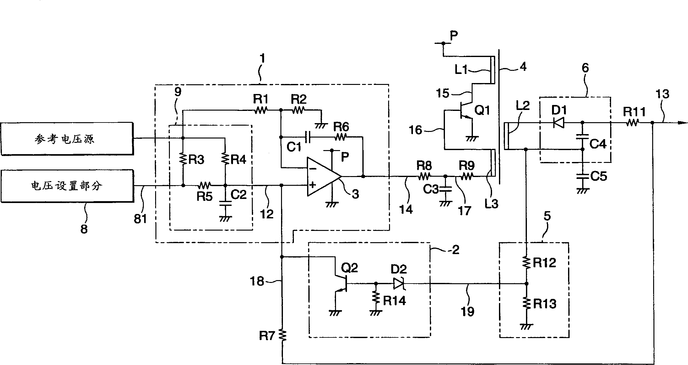
[0037] figure 1 is a circuit diagram showing the electrical connection of the first embodiment of the high voltage generating circuit for a toner system printer according to the present invention, showing a structure in which the output voltage varies with a voltage of, for example, about -1100V. and Figure 7 The same elements in the Figure 7 same label.

[0038] figure 1 Among them, the reference voltage source 7 is a component for outputting a voltage that is accurately stabilized to, for example, 10V. Also, the voltage setting section 8 is a part for setting the voltage of the secondary output 13 and for setting the voltage of the secondary output 13 at the duty ratio of the PWM signal to be output. The output of the voltage setting section 8 is an open-drain output.

[0039] The voltage control circuit 1 is a means for sending a DC voltage contro...


PUM


Abstract

In a structure including a voltage control circuit 1 for changing a voltage control signal 14 to control an oscillation amplitude of a transistor Q1 for oscillation, thereby stabilizing a voltage of a secondary output 13, there are provided a load suppressing circuit 5 for restricting a lower limit of a load impedance of a secondary coil L2 to prevent the oscillation of the transistor for oscillation from being stopped when the secondary output 13 is short-circuited, and an intermittent control circuit 2 for repeating an operation for reducing a voltage of the voltage control signal 14 to stop the oscillation when detecting a short circuit of a load and for raising the voltage of the voltage control signal 14 to restart the oscillation after stopping the oscillation.

Description

technical field [0001] The present invention relates to a toner system printer, such as a laser system printer or a copier, which performs printing by using toner, and more particularly to a high voltage generating circuit for generating high voltage required for toner system printing. Background technique [0002] JP-A-63-87173 has disclosed a conventional technique of changing the switching operation to intermittent operation to prevent the breakdown of the oscillating element when the output is short-circuited in the switching power supply. In this technique, a resistor for sensing current is inserted into the current path of the emitter of the switching transistor. When the voltage of the emitter exceeds a predetermined voltage, the current of the switching transistor is controlled to be a constant current. Also, a comparator for detecting the load circuit is provided. When a short circuit is caused, the switching operation of the switching transistor is stopped by the...

Claims


Application Information

Patent Timeline
Patent Type & Authority Applications(China)
IPC IPC(8): G03G15/00H02M3/338
CPCG03G15/80H02M3/3385
Inventor 樋口善男
Owner FUNAI ELECTRIC CO LTD
Why Eureka
Try Eureka