Cathode-ray tube

A cathode ray tube, diagonal technology, applied in the direction of cathode ray tube/electron beam tube, cathode ray/electron beam tube shell/container, discharge tube, etc., can solve the problem of reducing productivity, high investment, increasing product cost, etc. question

Inactive Publication Date: 2002-05-01
LG ELECTRONICS INC
View PDF0 Cites 1 Cited by
  • Summary
  • Abstract
  • Description
  • Claims
  • Application Information

AI Technical Summary

Problems solved by technology

However, improving furnace temperature requires prohibitive investment and reduces productivity and increases product cost

Method used


Image

  • Cathode-ray tube
  • Cathode-ray tube
  • Cathode-ray tube

Examples


Embodiment Construction

[0019] Hereinafter, preferred embodiments of the present invention shown in the accompanying drawings will be described in detail.

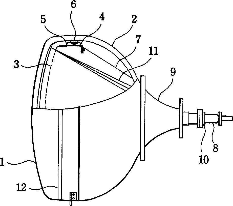
[0020] Based on the fact that the thickness difference caused by its wedge rate causes a considerable irregular temperature distribution in the welding part of the diagonal corner of the panel, the inventors conducted tests according to the temperature change in the welding sealing furnace to find out Key Factors Affecting CRT Recycling. Figure 5 It is a curve representing the furnace process specification in the fusion sealing process. The factors of heating rate, soak time, cooling rate and peak temperature can be found from this curve. Test in the following way: as in image 3 As shown, the products that have passed through the sealed furnace are recovered, and these products pass through the sealed furnace at different specified times. The results are shown in Table 1 below. Among them, the same recovery process was used for all products...


PUM


Abstract

There is provided a cathode-ray tube including an envelope having a neck, a funnel and a panel fused to the funnel by using frit glass, the outside of the panel being near flat, the inside of the panel having a predetermined curvature, in which 1.7<=T2 / T1<=2.3 when T1 is the thickness of the center of the panel and T2 is the thickness of the diagonal corner of the panel, and a panel inside tensile stress at the fused portion of the panel and funnel is less than -1.3876x+128.24 (Kgf / cm2) when the size of the effective picture area of the cathode-ray tube is x(unit: cm). The panel inside tensile stress at the fused portion of the panel and funnel is maintained below a predetermined value to mitigate breakage inside the furnaces that occurs when the cathode-ray tube having the panel whose outside is near flat and whose inside has a predetermined curvature is reproduced, thereby improving the salvage rate.

Description

technical field [0001] The present invention relates to a cathode ray tube with a flat outer surface panel, in particular to a planar cathode ray tube which artificially changes the stress distribution of the welded part of the panel and the cone to improve the recovery rate of glass in the recovery process. Background technique [0002] Such as figure 1 As shown, a cathode ray tube generally includes: a panel 1 arranged at its front; a shadow mask 3 for selecting the color of electron beams emitted into the panel 1; a frame 4 for fixing and supporting the shadow mask 3; the frame 4 A cylindrical pin 6 fixed on the panel 1; a cone 2 engaged with the panel 1 to maintain the vacuum state in the cathode ray tube; a spring 5 connecting the columnar pin 6 with the frame; a tubular neck 10 on the rear side of the cone 2 ; the electron gun 8 that is arranged in the neck 10 to emit the electron beam 11; the inner shield 7, which is combined with the frame 4 to shield the external m...

Claims


Application Information

Patent Timeline
Patent Type & Authority Applications(China)
IPC IPC(8): H01J29/86
CPCH01J29/861H01J2229/862
Inventor 丁圣翰
Owner LG ELECTRONICS INC
Why Eureka
Try Eureka