
In-situ analyzer of gas pollutants

An on-site analysis, micro-quantity technology, applied in the direction of measuring devices, sampling devices, analysis materials, etc.

Inactive Publication Date: 2002-05-01
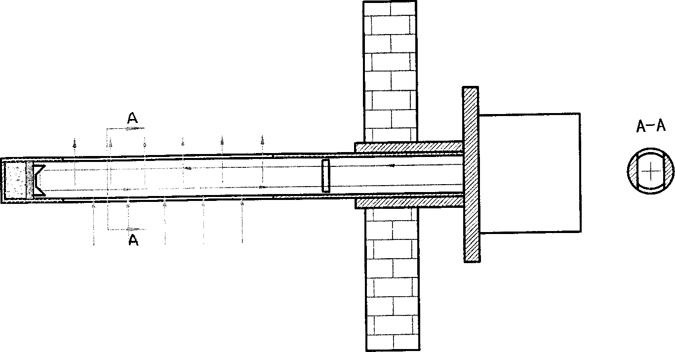
韩宏峰 +1
View PDF0 Cites 7 Cited by
  • Summary
  • Abstract
  • Description
  • Claims
  • Application Information

AI Technical Summary

Problems solved by technology

[0012] The object of the present invention is to provide an on-site analysis device for extracting a small amount of gaseous pollutants, which thoroughly solves most of the problems existing in the previous analysis systems

Method used


Image

  • In-situ analyzer of gas pollutants
  • In-situ analyzer of gas pollutants
  • In-situ analyzer of gas pollutants

Examples


Embodiment Construction

[0019] Refer below Figure 5 The micro-extraction on-site analysis device will be described in detail.

[0020] The on-site micro extraction analysis device of the present invention includes a mirror 60 , a filter set 58 , an infrared light source 59 , an infrared detector 62 , a lens 61 and an optical absorption cavity 54 . The use of these components belongs to common knowledge in the technical field, so their description is omitted.

[0021] The present invention is characterized in that it also includes: a coarse filter 51, a fine filter 52 and a fine filter 53 connected in sequence at the inlet end of the optical absorption cavity 54; a critical air extraction hole 55 arranged on the wall of the optical absorption cavity 54; And a vacuum pump 56, through the critical pumping holes 55 arranged on the tube wall of the optical absorption cavity 54 to extract the gas in the optical absorption cavity 54.

[0022] Calibration gas pipeline 57 is used for calibration (belonging...


PUM

PropertyMeasurementUnit
pore sizeaaaaaaaaaa

Abstract

An in-situ analyzer of gas pollutants by micro sampling is composed of a reflector, a filter set, an infrared ray source, an infrared detector, lens, an optical absorbing cavity, the coarse, fine and superfine filters at gas inlet of the optical absorbing cavity, critical gas-pumping hole on the wall of the optical absorbing cavity, and a vacuum pump for said critical gas-pumping hole. Its advantages are high precision, unique structure and high sampling reliability.

Description

technical field [0001] The invention relates to an analysis device for gaseous pollutants in flue gas, in particular to an on-site analysis device for extracting trace amounts of gaseous pollutants. Background technique [0002] Traditional flue gas analysis techniques can be classified into the following three categories: [0003] 1) In-situ technology, also known as direct analysis technology. [0004] The analysis method adopted by this technology is the mature infrared absorption method, and the sampling method is direct sampling in the chimney or flue. The sampling probe has two structural forms, figure 1 is open, figure 2 is closed. [0005] Domestic Peony Group has developed a direct analysis device, see figure 1 , its analysis cavity is open, and its problem is that the optical path is exposed in the smoke, and the on-site calibration of the analysis device cannot be completed. The pollution of the optical mirror by smoke and dust in the flue gas is serious, a...

Claims


Application Information

Patent Timeline
Patent Type & Authority Applications(China)
IPC IPC(8): G01N1/24G01N21/3518
Inventor 田东海韩宏峰
Owner 韩宏峰
Learn More