Standpipe inlet for enhancing particulate solids circulation for petrochemical and other processes

A standpipe, particle technology, used in chemical instruments and methods, petroleum industry, chemical/physical processes, etc., can solve problems such as air consumption, air bubble inhalation, etc.

Inactive Publication Date: 2002-03-20
SHELL INT RES MAATSCHAPPIJ BV
View PDF1 Cites 0 Cited by
  • Summary
  • Abstract
  • Description
  • Claims
  • Application Information

AI Technical Summary

Problems solved by technology

The main drawback of the prior art is that the standpipe inlet design aims to reduce the amount of gas entrained into the standpipe, in fact, this design instead encourages a large number of air bubbles to be sucked in
First, gas entrainment from the stripper into the ...

Method used


Image

  • Standpipe inlet for enhancing particulate solids circulation for petrochemical and other processes
  • Standpipe inlet for enhancing particulate solids circulation for petrochemical and other processes
  • Standpipe inlet for enhancing particulate solids circulation for petrochemical and other processes

Examples


Embodiment Construction

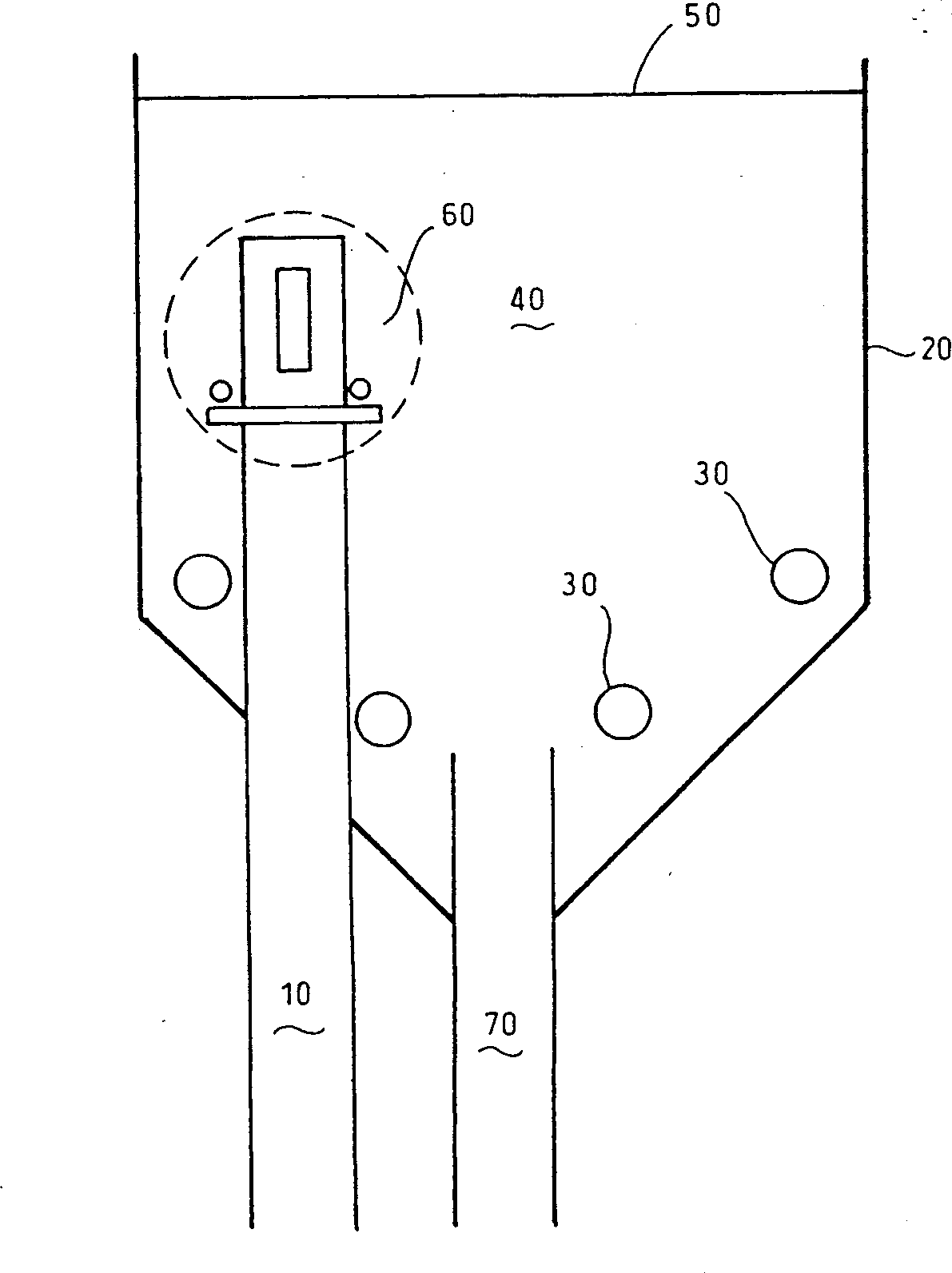
[0018] Reference figure 1 , figure 1 In accordance with the present invention, a cross-sectional view of the lower portion of a conventional regenerator vessel 20 of an FCC unit, wherein the FCC unit is provided with a regenerator standpipe 10 including an inlet portion 60 for sucking in the regenerated catalyst. The spent catalyst is transported from the stripper (not shown) through a conventional residual catalyst delivery pipe 70 and enters the regenerator 20. In the regenerator 20, the coke deposited on the catalyst is transported by the main air grille. The air burns away. The air from the grill 30 and the formed combustion gas rise through the regenerator so that the catalyst in the fluidized bed 40 is fluidized. The combustion gas and the entrained regenerated catalyst are separated by a cyclone (not shown) in the upper part of the regenerator. The combustion gas is discharged from the upper part of the regenerator, and the regenerated catalyst separated by the cyclone (not...


PUM


Abstract

Apparatus comprising means for keeping a bed of particulate solids in a fluidized bed mode in a vessel, a conduit for transferring said particulate solids into the resulting fluidized bed and a standpipe, protruding into said fluidized bed, for transferring particulate solids out of the fluidized bed, wherein a disk surrounding the standpipe is present below the upper part of the standpipe, which upper part the standpipe comprises an inlet for receiving solids from the fluidized bed.

Description

Technical field [0001] The present invention relates to a vertical pipe inlet structure for improving the circulation of particles and reducing gas migration. The inlet is suitable for fluidized bed catalytic cracking (FCC) units and other reactions, such as vulcanization coking units, softening coking units (flexicoker) and In the liquefied bed coal burner, a large amount of particulate solids circulate between different containers connecting a standpipe and a riser. Background technique [0002] A conventional fluidized-bed catalytic cracking (FCC) reaction usually includes a regenerator, a riser reactor and a stripper, as shown in US Patent No. 5562 818 issued to Hedrick, subdivided regeneration The catalyst stays in the regenerator and contacts the hydrocarbon feedstock in the lower part of the reactor riser. The hydrocarbon feedstock and steam enter the riser through the feed nozzle. A mixture of feed, steam, and regenerated catalyst at a temperature of about 200°C to about ...

Claims


Application Information

Patent Timeline
IPC IPC(8): B01J8/00B01J8/24B01J8/28C10G11/18F23C10/24
CPCB01J8/28C10G11/18F23C10/24B01J8/0015C10G11/182B01J8/003B01J8/1872B01J2208/00761B01J2208/00769
Inventor 戴维·J·布罗斯腾陈岳孟
Owner SHELL INT RES MAATSCHAPPIJ BV
Why Eureka
Try Eureka