Polarizing device for permanent magnet rotor
A rotor and permanent magnet technology, applied in the field of polarization devices, can solve the problems of large size of the current transmission unit, difficulty in demagnetization, difficulty in controlling current, etc.
- Summary
- Abstract
- Description
- Claims
- Application Information
AI Technical Summary
Problems solved by technology
Method used
Image
Examples
Embodiment 1
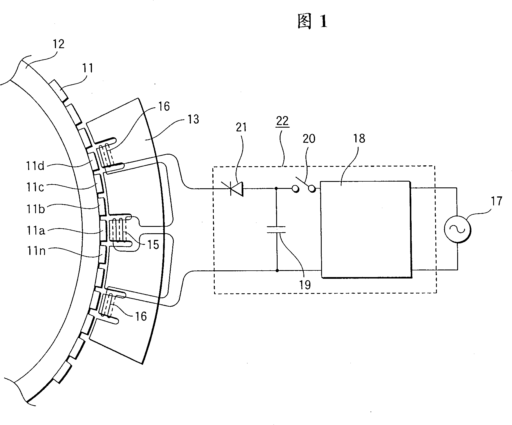
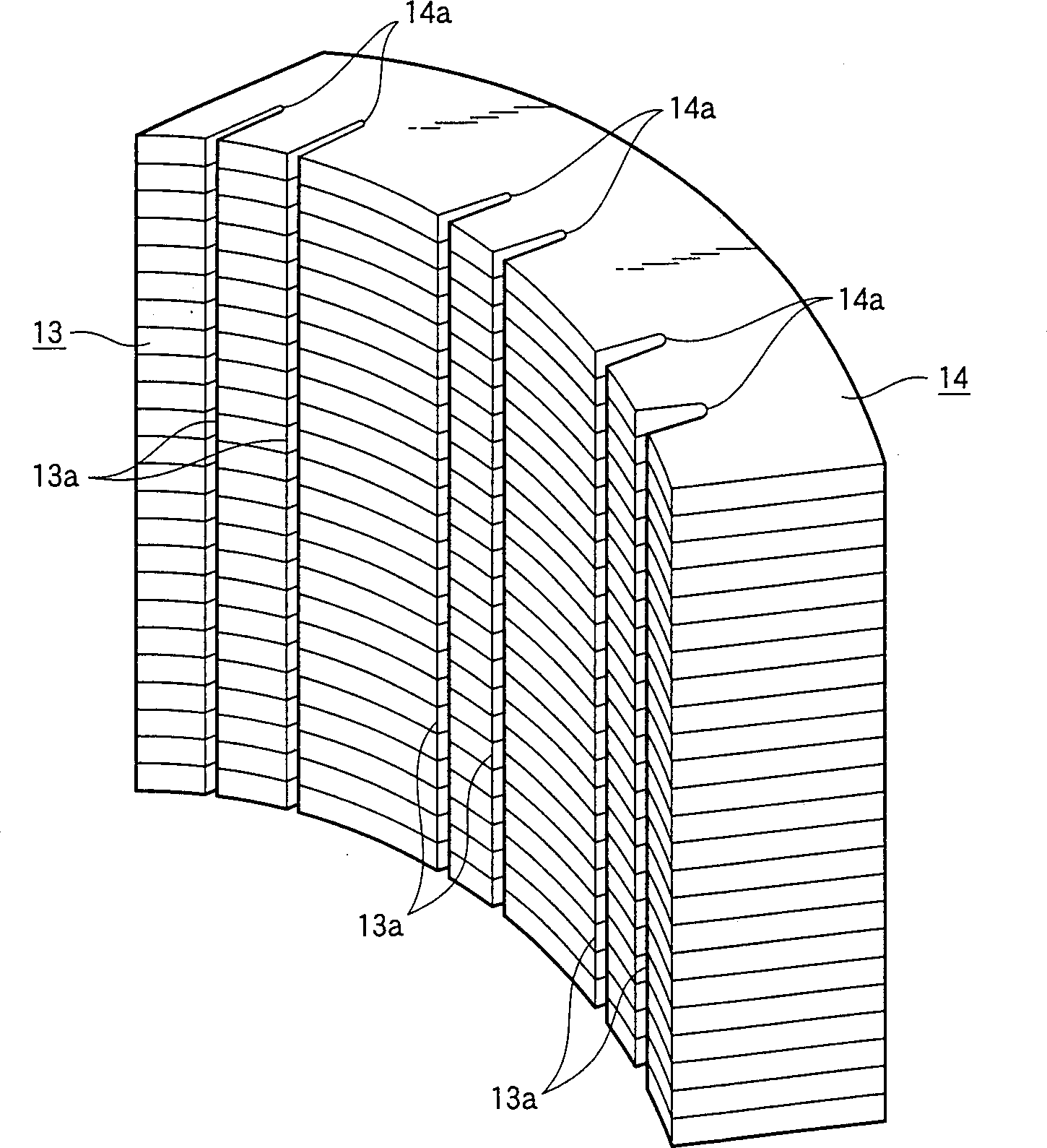
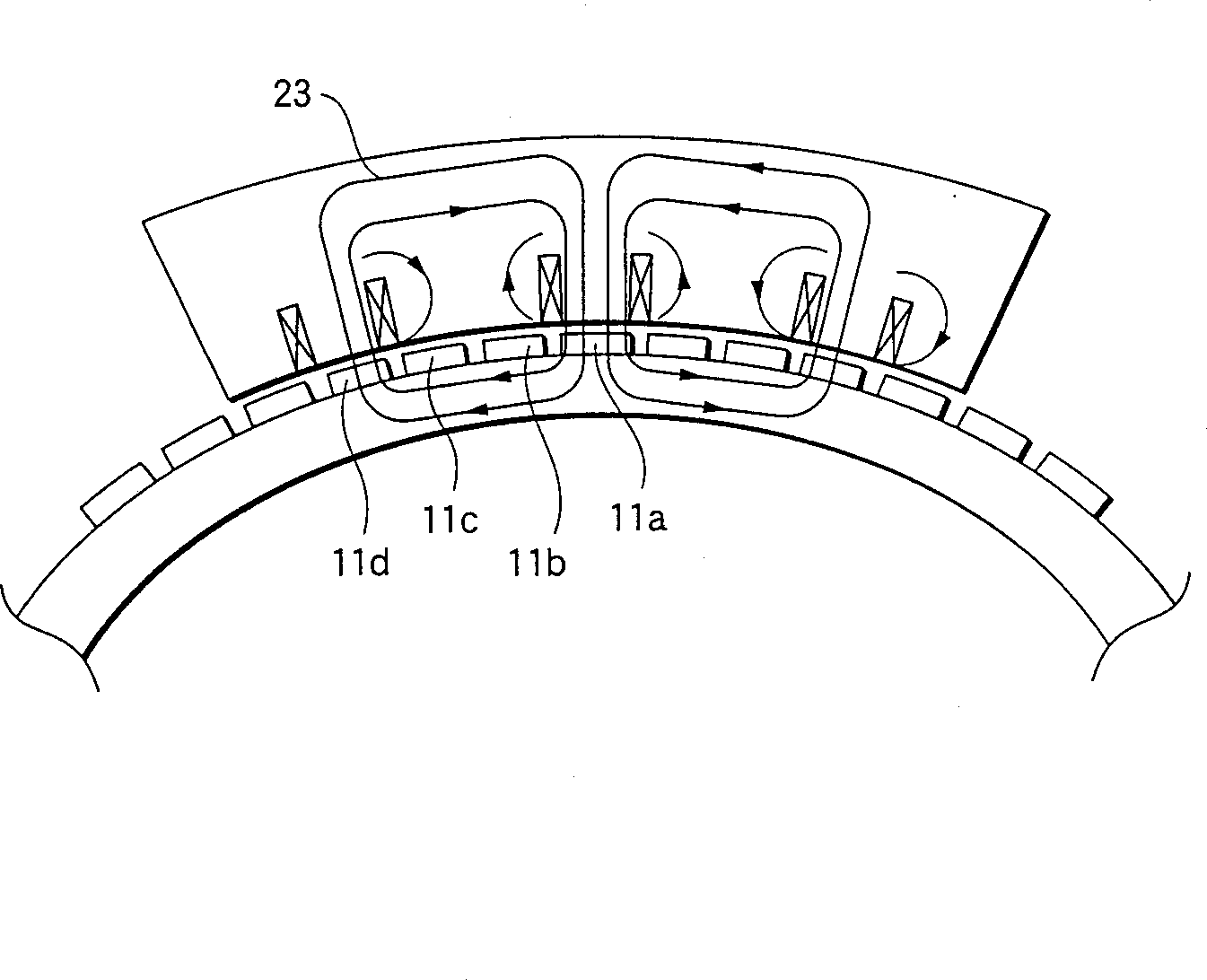
[0022] Accompanying drawing 1 shows the structural representation of the polarizing device of the permanent magnet rotor in Embodiment 1 of the present invention, appended figure 2 Shown is a perspective view of the structure of the polarized core of accompanying drawing 1, and the attached image 3 Shown is a state diagram of the magnetic flux distribution produced by the polarizing device of the permanent magnet rotor of FIG. 1 .
[0023] In this drawing, reference numeral 11 denotes a plurality of unmagnetized permanent magnets disposed on the outer surface of a rotor 12 at specific intervals in the circumferential direction, and reference numeral 13 denotes poles disposed to face a specific number of permanent magnets 11. iron core, as attached figure 2 As shown, it is formed by laminating a specific number of plate-shaped magnetic materials 14 on which notches 14a having a specific width and a specific depth are provided in pairs at three positions at specific interval...
Embodiment 2
[0035] attached Figure 4 Shown is a plan view of the structure of the main part of the polarizing device of the permanent magnet rotor in Embodiment 2 of the present invention.
[0036] In this drawing, the same reference numerals denote similar components to those in the described embodiment 1, and thus their descriptions are omitted.
[0037] Reference numeral 24 denotes a polarized core formed by laminating a plurality of plate-shaped magnetic materials, similarly to that in Embodiment 1 described (not shown), and notched portions 24a are formed near both sides of the first coil 15 to respectively Expand the gap with the permanent magnet 11.
[0038] Therefore, according to the above-described Embodiment 2, by forming the notch portions 24a in the vicinity of both sides of the first coil 15 of the polarized core 24 respectively, the gap with the permanent magnet 11 is expanded, thereby preventing the The magnetic flux forms a closed loop near the first coil 15 and prevents...
PUM
 Abstract
Description
Claims
Application Information
 - Generate Ideas
- Intellectual Property
- Life Sciences
- Materials
- Tech Scout
- Unparalleled Data Quality
- Higher Quality Content
- 60% Fewer Hallucinations
Browse by: Latest US Patents, China's latest patents, Technical Efficacy Thesaurus, Application Domain, Technology Topic, Popular Technical Reports.
© 2025 PatSnap. All rights reserved.Legal|Privacy policy|Modern Slavery Act Transparency Statement|Sitemap|About US| Contact US: help@patsnap.com


