Rotation angle detecting device
A technology of rotation angle detection and rotating magnets, applied in measuring devices, using electric/magnetic devices to transfer sensing components, converting sensor outputs, etc., can solve the problems of increased number of steps and increased manufacturing costs, and achieve the effect of reducing manufacturing costs
- Summary
- Abstract
- Description
- Claims
- Application Information
AI Technical Summary
Problems solved by technology
Method used
Image
Examples
no. 1 example
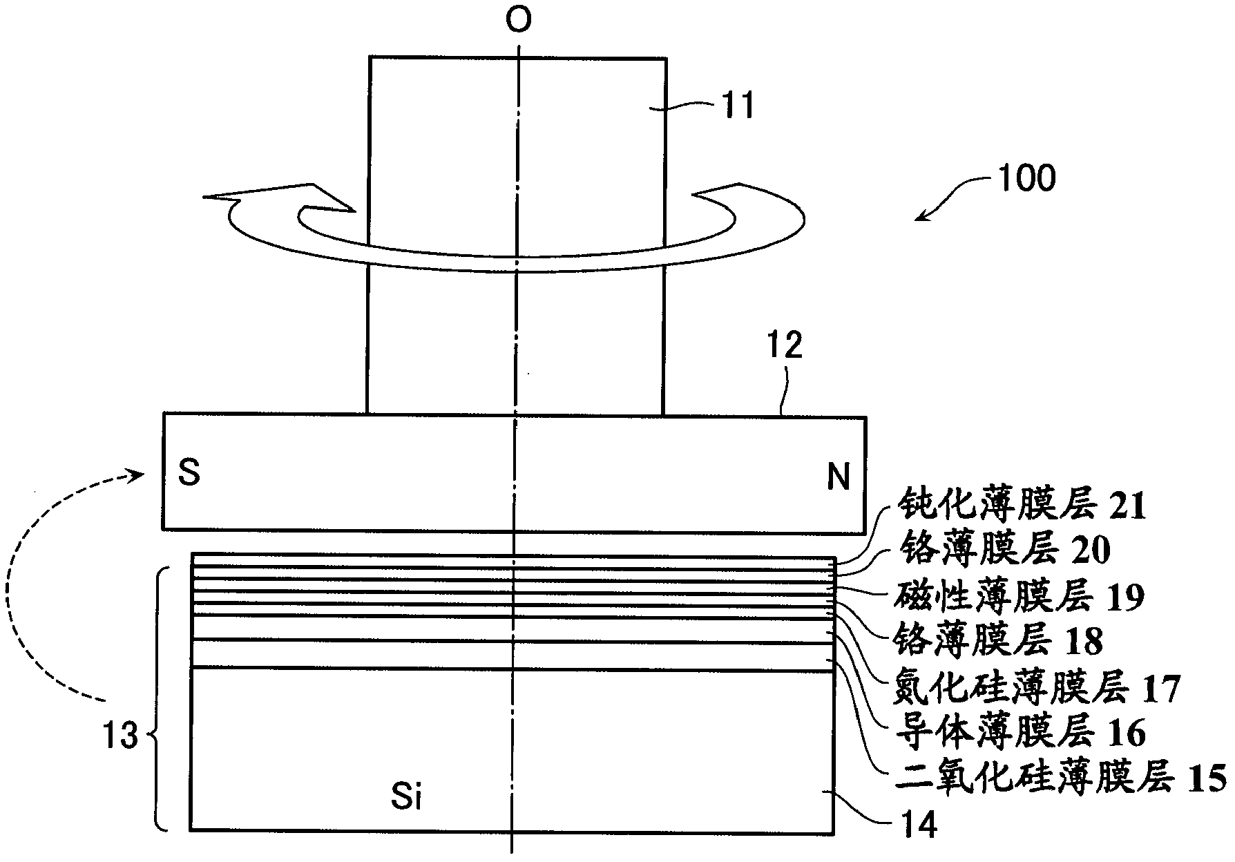
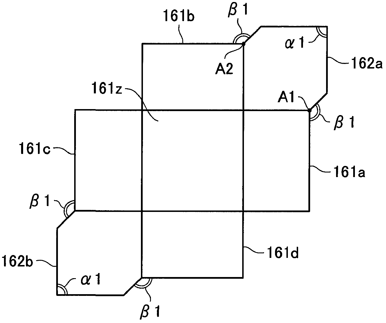
[0028] figure 1 is a side view showing the configuration of the rotation angle detection device 100 according to the first embodiment of the present invention. Figure 2A is a plan view of a quadrupole auxiliary magnet 160 as an example of a quadrupole auxiliary magnet included in the rotation angle detection device 100 . The rotation angle detection device 100 is configured to detect the rotation angle of a rotation shaft 11 of a power assist motor of, for example, an electric steering device of an automobile. A rotating magnet 12 is attached to an end of the rotating shaft 11 . The rotation angle detection element unit 13 is provided against the rotation magnet 12 in a non-contact manner. The rotation angle detection device 100 is configured by a rotation magnet 12 and a rotation angle detection element unit 13 .
[0029] The rotating magnet 12 is formed of a rectangular solid, and is a bipolar permanent magnet whose both ends in the longer direction are magnetic poles. ...
no. 2 example
[0057] Next, refer to Image 6 A rotation angle detection device according to a second embodiment of the present invention will be described. The overall configuration of the rotation angle detecting device according to the second embodiment is the same as that of the first embodiment ( figure 1 )same. However, this embodiment differs from the first embodiment in that it contains such Image 6 octopole auxiliary magnet 160a shown, instead of Figures 2A to 2E quadrupole auxiliary magnet. The eight-pole auxiliary magnet 160 a has a function of converting a rotating magnetic field of 0 to 360 degrees generated by the rotating magnet 12 into a rotating magnetic field of 0 to 90 degrees.
[0058] Since the second embodiment is otherwise identical to the first embodiment, no explanation is provided below for any identical portion.
[0059] Next, refer to Image 6 The configuration details of the eight-pole auxiliary magnet 160a are explained. The eight-pole auxiliary magnet ...
no. 3 example
[0070] Next, refer to Figure 7 A rotation angle detecting device according to a third embodiment of the present invention is explained. The overall configuration of the rotation angle detecting device according to the third embodiment is the same as that of the first embodiment ( figure 1 )same. However, this embodiment differs from the above-described embodiments in that it contains such Figure 7 The sixteen-pole auxiliary magnet 160b is shown as a multi-pole auxiliary magnet. The sixteen-pole auxiliary magnet 160b has a function of converting a rotating magnetic field of 0 to 360 degrees generated by the rotating magnet into a rotating magnetic field of 0 to 45 degrees. Since this embodiment is otherwise the same as the first embodiment, no explanation is provided below for any part that is the same.
[0071] Next, refer to Figure 7 The configuration details of the sixteen-pole auxiliary magnet 160b are explained. The sixteen-pole auxiliary magnet 160b includes a ra...
PUM
 Abstract
Description
Claims
Application Information
 - R&D Engineer
- R&D Manager
- IP Professional
- Industry Leading Data Capabilities
- Powerful AI technology
- Patent DNA Extraction
Browse by: Latest US Patents, China's latest patents, Technical Efficacy Thesaurus, Application Domain, Technology Topic, Popular Technical Reports.
© 2024 PatSnap. All rights reserved.Legal|Privacy policy|Modern Slavery Act Transparency Statement|Sitemap|About US| Contact US: help@patsnap.com


