
Polarizing device for permanent magnet rotor

A technology for magnetizing devices and rotors, applied in electromechanical devices, manufacturing stator/rotor bodies, magnetic objects, etc., can solve problems such as difficulty in demagnetization, large size of current delivery unit, and difficulty in controlling current

Inactive Publication Date: 2005-11-16
MITSUBISHI ELECTRIC CORP
View PDF2 Cites 2 Cited by
  • Summary
  • Abstract
  • Description
  • Claims
  • Application Information

AI Technical Summary

Problems solved by technology

[0006] The conventional magnetization device of the permanent magnet rotor realizes a miniaturized device, as described above, by magnetizing the magnetized iron core of one magnetic pole on which the coil is wound, while sequentially switching the parallel current flowing in the coil. Corresponding to the direction of the current of each unmagnetized permanent magnet, and magnetized into N pole or S pole, so as in the attached Figure 5 As shown in , the magnetic flux 3 is generated by the current flowing in the coil 2 wound on the magnetized iron core 1, and assuming that the corresponding unmagnetized permanent magnet 4a is magnetized into the S pole, from the magnetic flux 3 in this figure The distribution can be clearly seen that the magnetic flux 3 passes through the corresponding unmagnetized permanent magnets 4b, 4c in the vicinity of the unmagnetized permanent magnet 4a in the opposite direction to the magnetization direction, and in the opposite direction to the direction in which the magnetization should be performed Magnetization is performed, therefore, in the case where the magnetization is actually performed in the desired direction at the position corresponding to the magnetized core 1, demagnetization must be performed for the magnetization in the opposite direction, therefore, it is necessary to change the current flowing in the coil 2 every time, Therefore, there is a problem that it is difficult to control the current
[0007] In addition, in the case where the unmagnetized permanent magnet is a rare-earth magnet, demagnetization is difficult, and remagnetization requires a considerably stronger magnetic field than that of the unmagnetized region, so there is a problem that the size of the current delivery unit becomes large

Method used


Image

  • Polarizing device for permanent magnet rotor
  • Polarizing device for permanent magnet rotor
  • Polarizing device for permanent magnet rotor

Examples


Embodiment 1

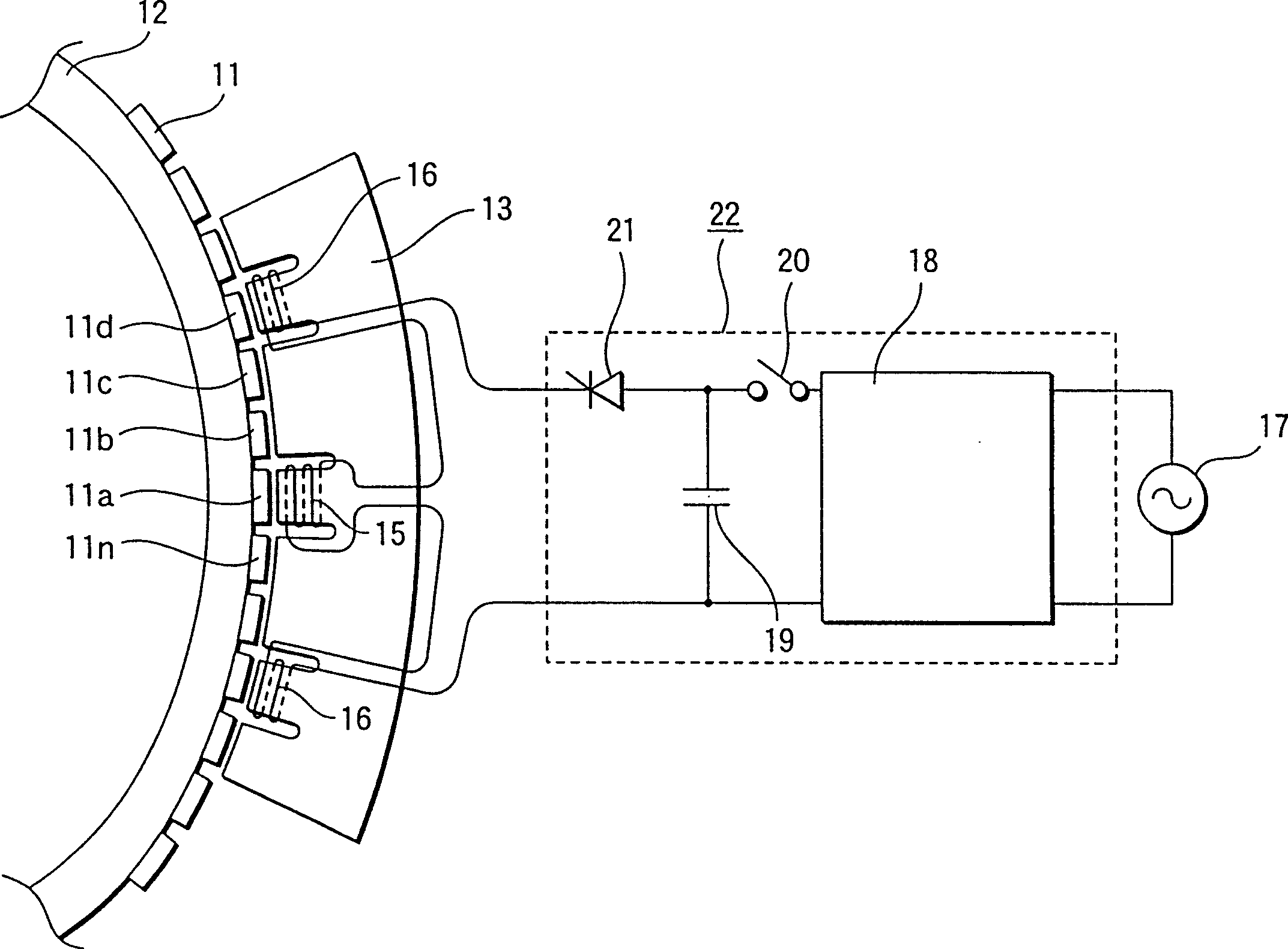
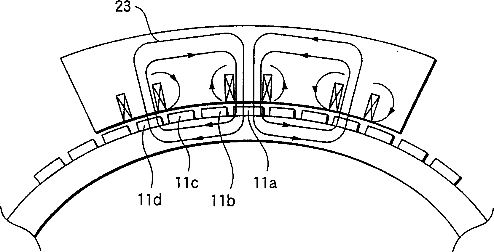
[0022] attached figure 1 Shown is a schematic structural view of the magnetization device of the permanent magnet rotor in Embodiment 1 of the present invention, with figure 2 shown attached figure 1 A perspective view of the structure of the magnetized core, and the attached image 3 shown by the attached figure 1 State diagram of the magnetic flux distribution generated by the magnetization device of the permanent magnet rotor.

[0023] In the drawing, reference numeral 11 denotes a plurality of unmagnetized permanent magnets arranged at specific intervals on the outer surface of the rotor 12 in the circumferential direction, and reference numeral 13 denotes magnetized magnetized magnets disposed facing a specific number of permanent magnets 11. Iron heart, as attached figure 2 As shown, it is formed by laminating a specific number of plate-shaped magnetic materials 14 on which notches 14a having a specific width and a specific depth are provided in pairs at three p...

Embodiment 2

[0035] attached Figure 4A plan view showing the structure of the main part of the magnetization device of the permanent magnet rotor in Embodiment 2 of the present invention is shown.

[0036] In this drawing, the same reference numerals denote similar components to those in the described embodiment 1, and thus their descriptions are omitted.

[0037] Reference numeral 24 denotes a magnetized core formed by laminating a plurality of plate-shaped magnetic materials, similarly to that in Embodiment 1 described (not shown), and notched portions 24a are formed near both sides of the first coil 15 to respectively expand Gap with permanent magnet 11.

[0038] Therefore, according to the above-described Embodiment 2, by forming the notch portions 24a in the vicinity of both sides of the first coil 15 of the magnetized core 24, respectively, the gap with the permanent magnet 11 is expanded, thereby preventing the magnetization caused by the first coil 15. The magnetic flux forms a ...


PUM


Abstract

A polarizing device includes: a polarizing iron core (13) facing to a specified number of permanent magnets (11) among plural unmagnetized permanent magnets (11) arranged at specified intervals circumferentially on a rotor (12); a first coil (15) wound at a position facing to a desired permanent magnet (11a) of the polarizing iron core (13); a pair of second coils (16) each arranged having a specified interval according to the first coil (15) circumferentially on the polarizing iron core (13) and whose direction of the flowing current is different from that of the first coil (15); and a power source (22) for supplying the current to the first and second coils (15, 16), and either of the permanent magnet (11a) and first coil (15) is relatively moved and each permanent magnet (11) is magnetized to form a magnetic pole in turn by the current fed from the power source (22).

Description

technical field [0001] The present invention relates to a magnetizing device in which unmagnetized permanent magnets provided on the peripheral surface of a rotor are sequentially magnetized to form magnetic poles. Background technique [0002] Previously, among the magnetic poles of the permanent magnet rotor, there were cases where permanent magnets were applied as the magnetic poles of the rotor in which the magnetic poles were assembled to the rotor after magnetization, and there were also cases in which unmagnetized magnetic poles that had not been magnetized were assembled It is magnetized and magnetized after reaching the rotor. [0003] However, in the case of magnetizing the magnetic poles before assembling into the rotor, the assembly work becomes difficult due to strong suction force, so in larger-sized rotors, the magnetic poles are usually magnetized after assembly. [0004] As a conventional magnetizing device for this type of permanent magnet rotor, for examp...

Claims


Application Information

Patent Timeline
Patent Type & Authority Patents(China)
IPC IPC(8): H02K15/00H01F13/00H02K15/03
CPCH01F13/003H02K15/03H02K15/00
Inventor 石见泰造梶田直树鱼住尚功
Owner MITSUBISHI ELECTRIC CORP
Learn More