
Cord tension control apparatus

A tension control and cable technology, applied in the control system, control generator, control multiple AC motors, etc., can solve problems such as the inability to maintain constant current, and achieve the effect of effective utilization

Inactive Publication Date: 2007-04-25
NITTA CORP
View PDF4 Cites 0 Cited by
  • Summary
  • Abstract
  • Description
  • Claims
  • Application Information

AI Technical Summary

Problems solved by technology

[0008] For this reason, the necessary voltage cannot be ensured to make a constant current flow in the constant current circuit, and the constant current cannot be maintained.

Method used


Image

  • Cord tension control apparatus
  • Cord tension control apparatus
  • Cord tension control apparatus

Examples


Embodiment Construction

[0023] Hereinafter, embodiments of the present invention will be described in detail with reference to the drawings.

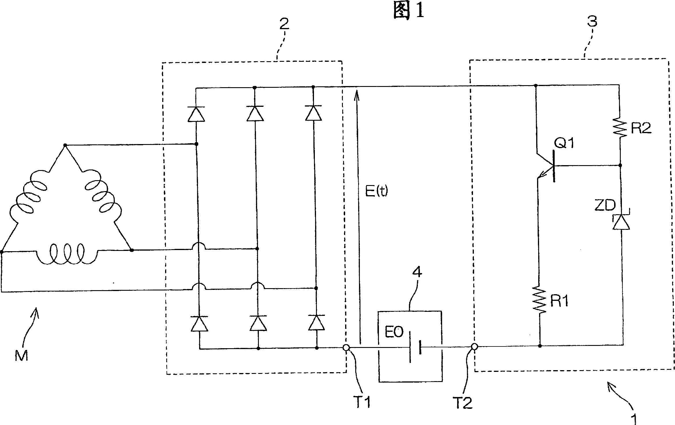
[0024] Fig. 1 is a circuit diagram showing an example of the tension control device of the present invention.

[0025] The tension control device 1 rectifies the output voltage of a three-phase brushless motor (hereinafter referred to as “brushless motor”) M through a rectifier circuit 2 , and supplies the rectified output to a constant current circuit 3 . The rectifier circuit 2 and the constant current circuit 3 can be assembled on the internal substrate of the brushless motor M to rotate together with the motor rotation shaft, or can be installed outside the brushless motor M. In FIG. 1, they are built in the brushless motor The examples in M ​​illustrate.

[0026] The output voltage of the rectifier circuit 2 fluctuates according to the fluctuation of the rotational speed of the brushless motor M. As shown in FIG. Therefore, the output voltage of the rec...


PUM


Abstract

A cord tension control apparatus includes a brushless motor (M) generating counter electromotive force, a rectifier circuit (2) connected to a winding of the brushless motor (M), and a constant current circuit (3) connected to the rectifier circuit (2). A voltage circuit (4) giving forward direction bias voltage is inserted between the constant current circuit (3) and the rectifier circuit (2). Even when the rotation speed of the motor (M) is lowered and the output voltage is lowered, at least the forward direction bias voltage generated by the voltage circuit (4) is applied to the constant current circuit (3). Accordingly, there is no non-operation state of the constant current circuit (3) when the rotation speed of the motor (M) is lowered. A constant current can be assured and the tension of cords can be controlled to be always constant.

Description

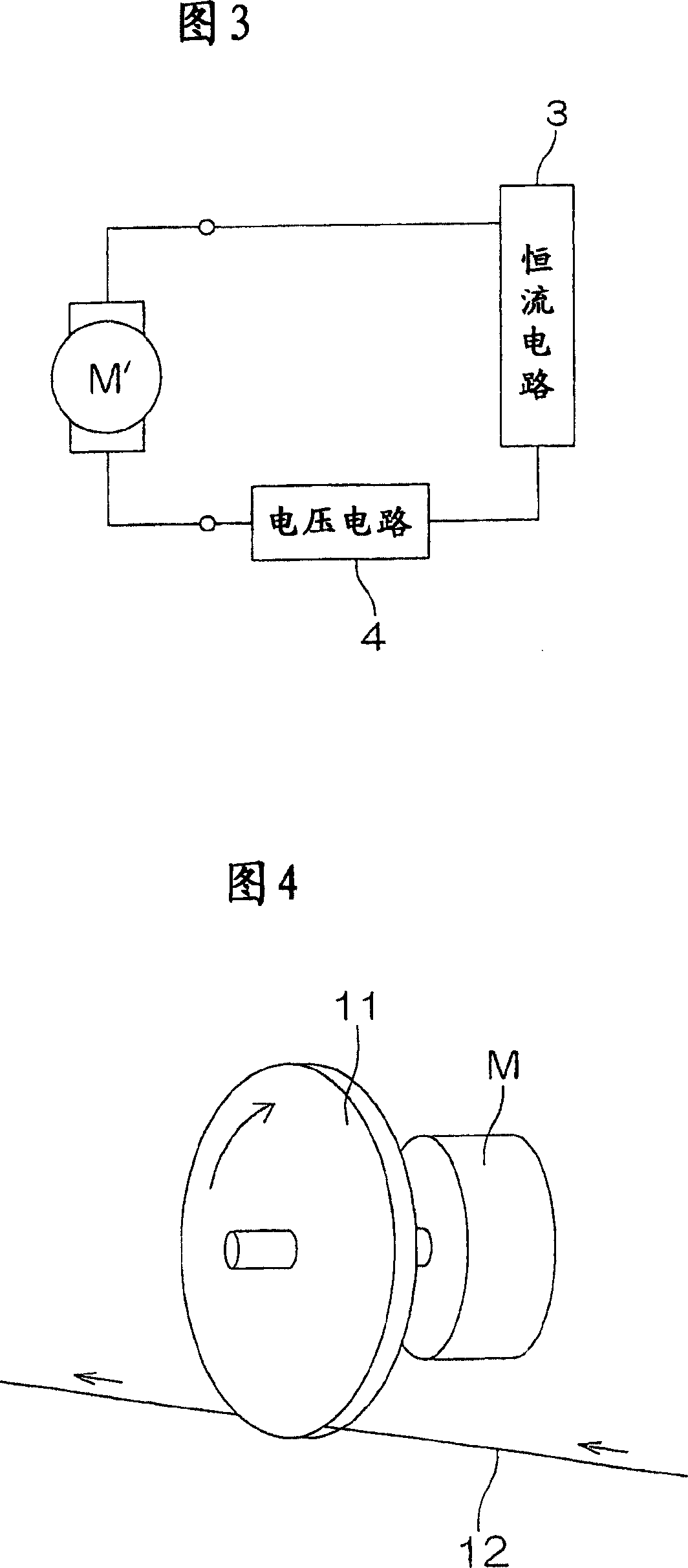
technical field [0001] The present invention relates to a cable-type tension control device for applying a constant tension to cables such as wires, tapes, ribbons, and electric wires. Background technique [0002] The cable tension control device is used in coilers and the like for winding wires, and can realize winding of wires with a constant tension. [0003] As shown in FIG. 4 , this tension control device includes a stretching pulley 11 and a motor M provided coaxially with the stretching pulley 11 and rotating simultaneously. When the wires 12 run, the motor M is rotated via the tension pulley 11, and tension is given to the wires 12 by the torque generated in the motor M. [0004] The above-mentioned electric motor M generates a counter electromotive voltage when rotation is applied. If this counter electromotive force voltage is input to the constant current circuit built in the motor M, the torque becomes constant regardless of the rotation speed of the motor, an...

Claims


Application Information

Patent Timeline
Patent Type & Authority Patents(China)
IPC IPC(8): H02P6/08B65H59/10B65H59/38B65H59/40H02P5/74H02P9/10
CPCH02P9/10B65H59/40B65H59/384H02P5/74B65H2601/12
Inventor 王国华栗田康史
Owner NITTA CORP
Learn More