Differential line driver

A line driver and driver technology, applied in the direction of differential amplifiers, line transmission components, circuits, etc., can solve problems such as instability and low signal bandwidth

Inactive Publication Date: 2001-07-18
TELEFON AB LM ERICSSON (PUBL)
View PDF0 Cites 5 Cited by
  • Summary
  • Abstract
  • Description
  • Claims
  • Application Information

AI Technical Summary

Problems solved by technology

Improper compensation in line drivers can lead to low signal bandwidth and / or instability

Method used


Image

  • Differential line driver
  • Differential line driver
  • Differential line driver

Examples


Embodiment Construction

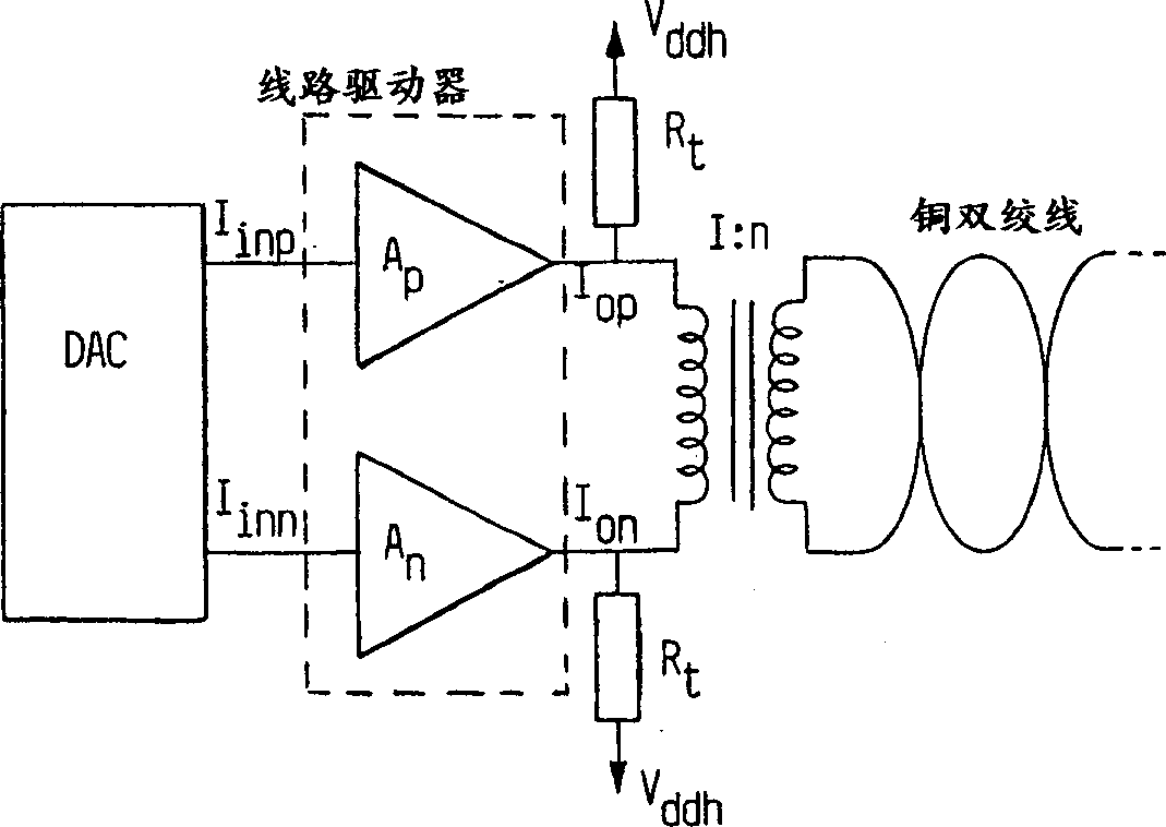
[0017] The general concept of the invention can be explained by figure 2 come to understand. A line driver is configured with a pair of current inputs I inp and I inn . The line driver (in the dotted rectangle) has a pair of current outputs configured with a ddh and connected to the terminal resistor R of the transformer coil t , while the other coil is connected to the copper twisted pair. Obviously, there is also a set of two current amplifiers A in the dotted rectangle p and A n .

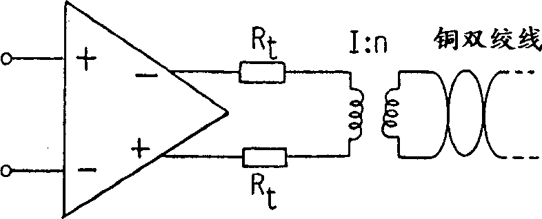
[0018] The line driver itself will have a very low input impedance in order to interface easily with a driving DAC. Different from the conventional scheme shown in Fig. 1, the line driver proposed by the present invention has a very high output impedance. With a low input impedance and a high output impedance, the line driver is a current-mode line driver. Port resistors at the output of the line driver will give a high common-mode rejection and impedance matching.

[0019] The effect...


PUM


Abstract

A fully differential line driver, especially for twisted copper pairs. It comprises two current amplifiers (Ap, An), made in standard CMOS technique, each having an input (Iinp, Iinn) and an output (Iop, Ion), which latter are connected via terminal resistors (Rt) to a voltage source, which may be set to a larger voltage than that used for driving the CMOS amplifiers. With this invention, a low output impedance can be combined with a large swing. Further, feedback is not necessary, avoiding problems like potential instability. A preferred embodiment also has a very low-impedance input, making it appropriate for connecting to a DAC, thus reducing distortion of its output signal. The invention is suitable for very-high-speed-digital-subscriber-line modems.

Description

Background of the invention [0001] The invention relates to a CMOS differential line driver, in particular, it is used to drive a line comprising a copper twisted pair, and has a differential analog output terminal comprising two input terminals and two output terminals. This is primarily a consideration for the use of copper twisted pair wires for high speed applications such as high speed Internet access. [0002] A conventional type of fully differential line driver is schematically shown in Figure 1. The electric energy is fed into the copper twisted pair 1 through the transformer 2 . In order to obtain impedance matching, the transformation impedance of the copper twisted pair must match the port resistance R t match. [0003] A complete description of one embodiment is given in Khorramabadi's paper published in IEEE J. Solid-State Circuits, Vol. 27 No. 4, (1992) p. 539. In the paper "Integrated Circuits for Data Transmission over Twisted-Pair Channels" by Johns and E...

Claims


Application Information

Patent Timeline
Patent Type & Authority Applications(China)
IPC IPC(8): H03F3/45H01L27/00H03B1/00H03F1/56H04BH04B3/02H04LH04L25/02H05K3/00
CPCH04L25/0266H03M1/80
Inventor T·念雄J·埃尔兰德斯J·维克纳
Owner TELEFON AB LM ERICSSON (PUBL)
Why Eureka
Try Eureka