Magnetic fluid seal device
A magnetic fluid and sealing device technology, applied in the direction of engine sealing, engine components, mechanical equipment, etc., can solve the problems of lack of responsiveness and inability to ensure sealing.
- Summary
- Abstract
- Description
- Claims
- Application Information
AI Technical Summary
Problems solved by technology
Method used
Image

Examples
no. 1 Embodiment approach
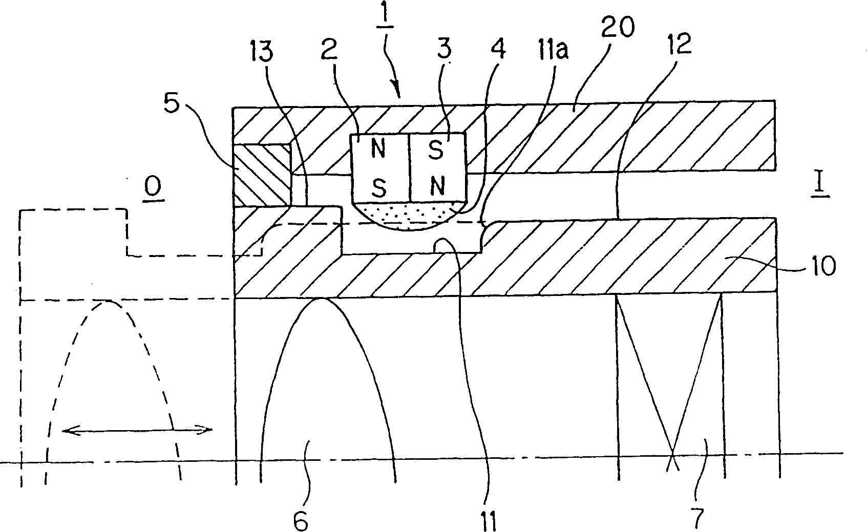
[0053] use figure 1 The structure in which the light-shielding device according to the first embodiment is used in a compact camera will be described. in addition, figure 1 It is a schematic enlarged view of the zoom lens part of a pocket camera.
[0054] figure 1 The zoom lens unit of the compact camera shown in , includes: an outer lens barrel 20 provided on the camera body; and a lens barrel 10 provided inside the outer lens barrel 20 and reciprocating so as to protrude from the camera body. The two connected lens barrels 10 , 20 are two parts that can be relatively reciprocated and assembled. In addition, the zoom lens unit further includes a lens 6 and a shutter unit 7 arranged inside the inner barrel 10 .
[0055] The inner lens barrel 10 is a member that performs relative reciprocating movement from the stored state (stopped state) to the outer side O (shown by a dotted line in the figure) or back to the stored state by a zoom operation.
[0056] That is, the lens ba...
no. 2 Embodiment approach
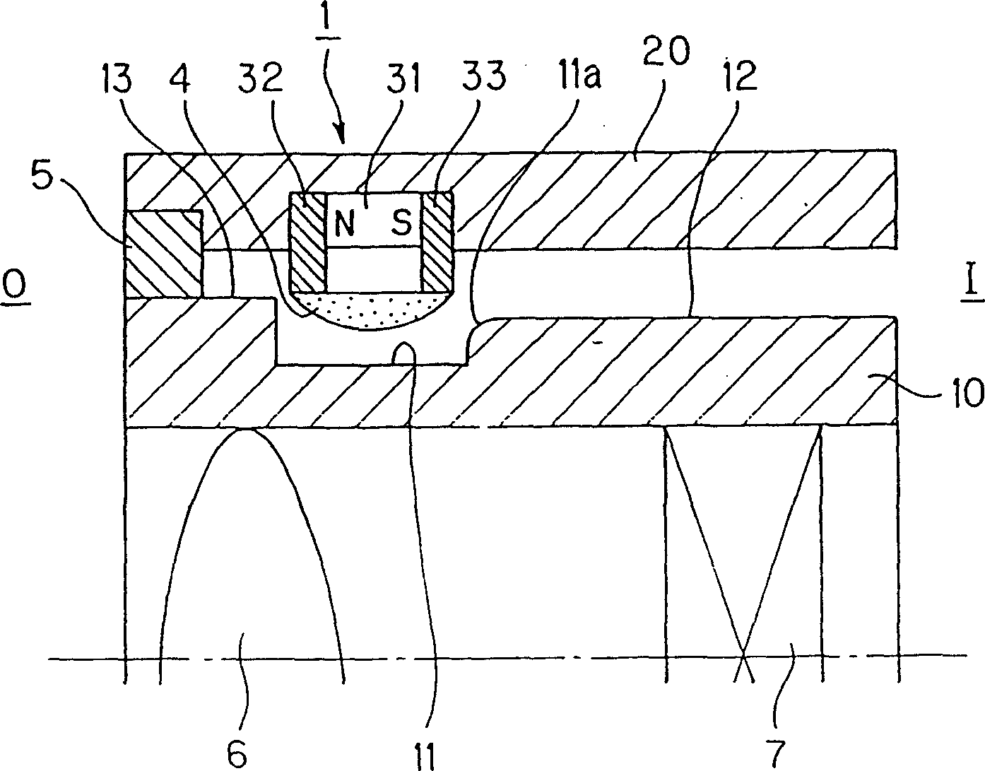
[0082] figure 2 Shown is the shading device according to the second embodiment. The second embodiment is one in which the configuration of the magnetic circuit forming device is changed. Other configurations are the same as those of the first embodiment.
[0083] The magnetic circuit forming device is composed of a ring magnet (magnetic force generating element) 31 magnetized in the axial direction; and a pair of magnetic pole pieces 32 and 33 composed of magnetic bodies fixed at both ends of the ring magnet in the axial direction.
[0084] Furthermore, the magnetic fluid 4 is held between the inner peripheral end portions of the pair of magnetic pole pieces 32 and 33 .
[0085] In this way, the configuration of the magnetic circuit forming device can be changed according to the application or installation space.
no. 3 Embodiment approach
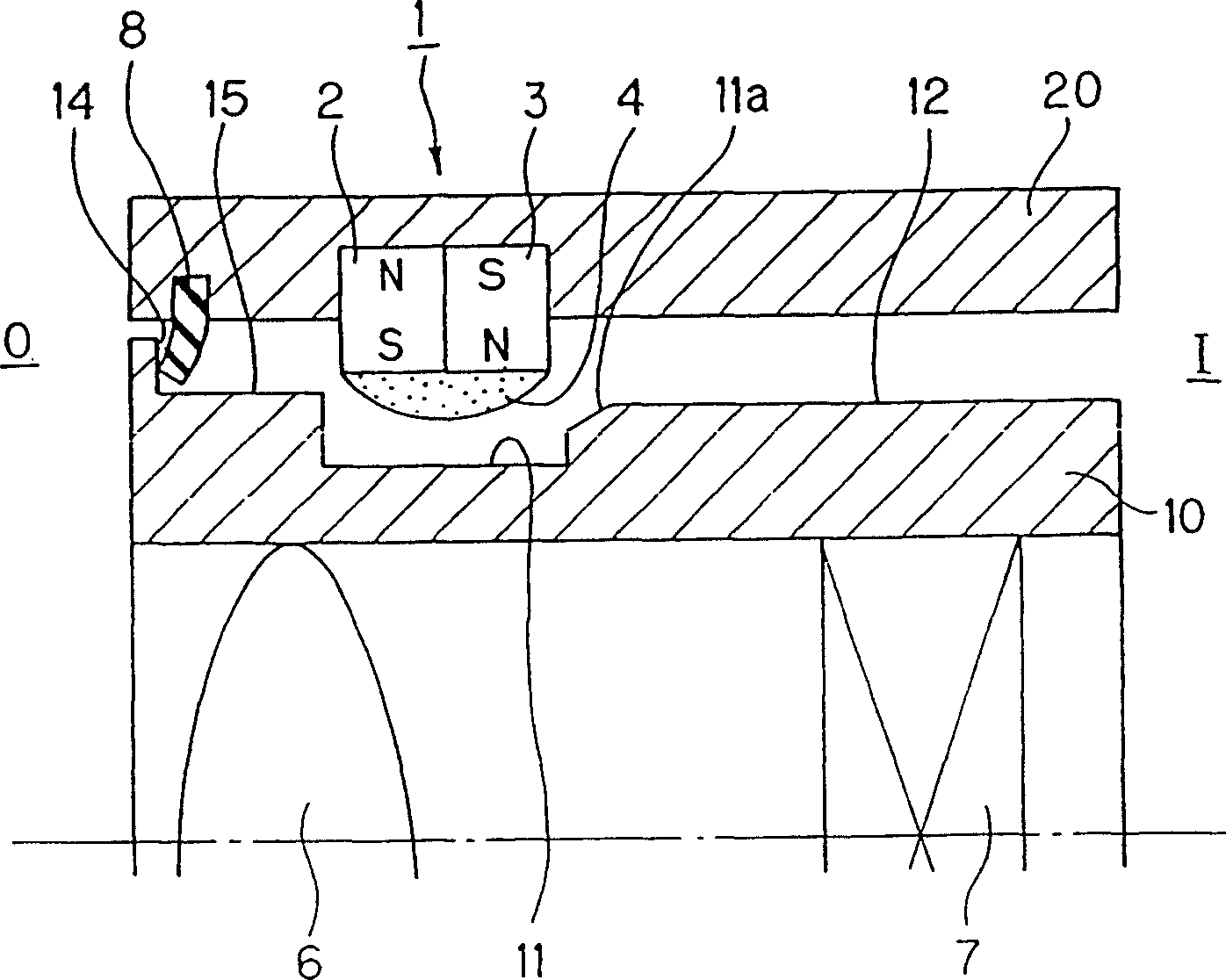
[0087] image 3 Shown is the shade device according to the third embodiment. Here, the characteristic parts of the shading device 1 according to the third embodiment will be described, and the other structures that are the same as those in the first embodiment will be denoted by the same reference numerals and descriptions will be omitted.
[0088] In the third embodiment, the sealing member 8 is arranged on the outer side of the pair of ring magnets 2, 3 on the inner peripheral surface of the lens barrel 20, and is formed in a ring shape by an elastic body material such as rubber, and its inner peripheral front end is made to face outward. side curved shape. In addition, the inner peripheral front end of the sealing member 8 does not reach the surface (area 15 ) of the outer peripheral surface of the lens barrel 10 . Other functions of the sealing member 8 are the same as those of the sealing member 5 of the first embodiment.
[0089] Moreover, in the stored state, the sea...
PUM
 Abstract
Description
Claims
Application Information
 - R&D
- Intellectual Property
- Life Sciences
- Materials
- Tech Scout
- Unparalleled Data Quality
- Higher Quality Content
- 60% Fewer Hallucinations
Browse by: Latest US Patents, China's latest patents, Technical Efficacy Thesaurus, Application Domain, Technology Topic, Popular Technical Reports.
© 2025 PatSnap. All rights reserved.Legal|Privacy policy|Modern Slavery Act Transparency Statement|Sitemap|About US| Contact US: help@patsnap.com