Image signal processor and image signal processing method

An image signal processing and chrominance signal technology, applied in the direction of luminance and chrominance signal processing circuits, etc., can solve the problems of small luminance cross-color and can not be removed, and achieve the goal of reducing luminance cross-color, improving resolution, and suppressing color shedding. Effect

Inactive Publication Date: 2007-01-24
PANASONIC CORP
View PDF3 Cites 0 Cited by
  • Summary
  • Abstract
  • Description
  • Claims
  • Application Information

AI Technical Summary

Problems solved by technology

Therefore, it is possible to remove the signal in the case of inputting a minute slanted line of 1 wavelength or less (including 1 wavelength), but it cannot remove the signal when the slashed line is continuously input. The effect of distortion and cross-colour is very small

Method used


Image

  • Image signal processor and image signal processing method
  • Image signal processor and image signal processing method
  • Image signal processor and image signal processing method

Examples


Embodiment Construction

[0027] —The overall structure of the TV receiver

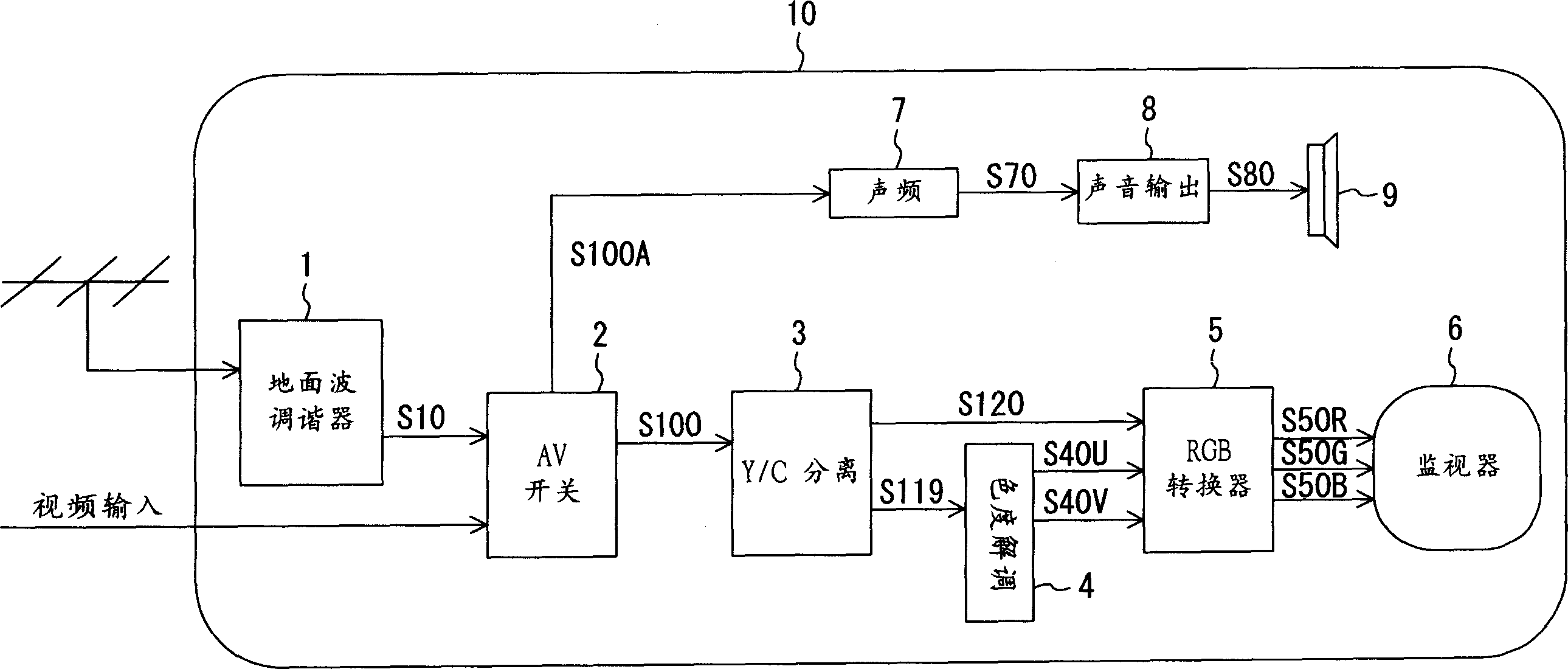
[0028] figure 1 This is a block diagram showing the overall structure of the television receiver according to the embodiment of the present invention. The television receiver 10 has: a terrestrial wave tuner 1, an AV switch 2, a Y / C separation device 3, a chrominance demodulation circuit 4, an RGB conversion circuit 5, a monitor screen 6, an audio processing circuit 7, a sound output circuit 8, and Horn 9.

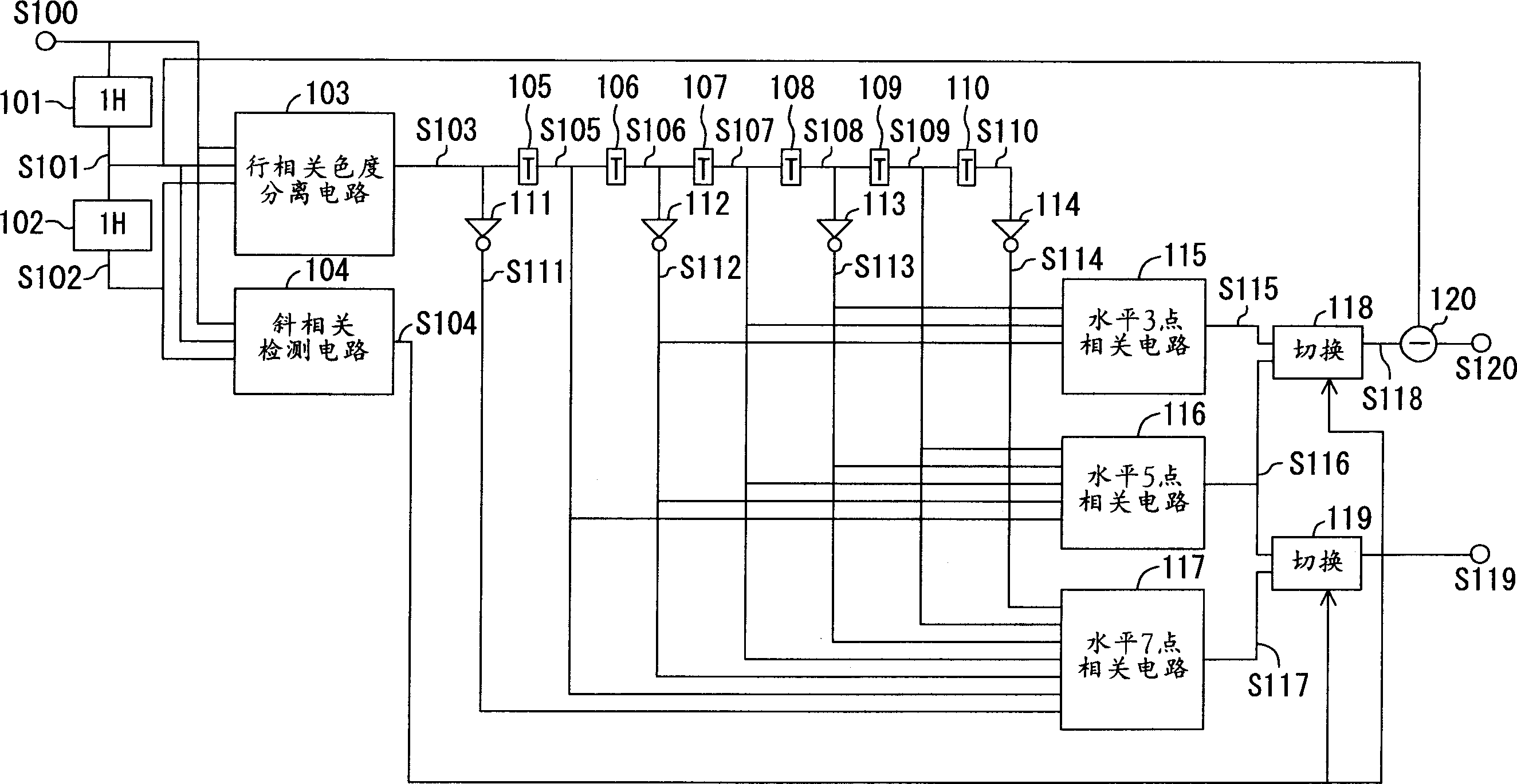
[0029] The terrestrial tuner 1 receives the TV program assigned to each channel; the AV switch 2 switches the terrestrial broadcast signal S10 received by the terrestrial tuner 1 and the image signal and sound signal input by the external equipment such as recorder and player; Y / C The separation device 3 separates the full TV signal S100 output from the AV switch 2 into a luminance signal S120 and a chrominance signal S119; the chrominance demodulation circuit 4 demodulates the chrominance signal output from the...


PUM


Abstract

Provided is a video signal processing device in which a cross color generated by the leakage of a brightness signal component into a color picture signal component is reduced, and a resolution in an oblique direction is improved even when not only a narrow oblique line but brightness signals correlated with an oblique direction are continuously inputted, and to provide a method therefor. This device comprises: an oblique component detection circuit for detecting an oblique component from an inputted composite video signal; a delay circuit for delaying an output signal of a color separator circuit by a time period of a half cycle; an inverting circuit for alternately inverting with an output signal of a center point of the delay circuit as a reference; a minimum value circuit for comparing output signals different from each other out of the output signal of the delay circuit and that of the inverting circuit to select a minimum value; and a maximum value circuit for selecting a maximum value from output signals of the minimum value circuit. By switching a horizontal correlation detection range, the cross color is reduced and the resolution is improved.

Description

Technical field [0001] The invention relates to a device and method for separating a luminance signal (Y) and / or a chrominance signal (C) from a full television signal. Background technique [0002] In recent years, with the increase in the size of television receivers and the development of image quality, more and more attention has been paid to Y / C separation devices (luminance signal / color signal) that separate the luminance signal from the chrominance signal from the entire TV signal. High-performance signal separation device). [0003] Next, the conventional Y / C separation device will be described. [0004] Picture 11 It is a block diagram showing the structure of the Y / C separation device disclosed in Japanese Patent Laid-Open No. 5-11051. in Picture 11 Here, the input terminal 31 is an input section of a chrominance signal with a limited band output from the interline comb filter. The delay circuits 32 to 35 are connected in series to the input terminal 31. The delay ci...

Claims


Application Information

Patent Timeline
Patent Type & Authority Patents(China)
IPC IPC(8): H04N9/78
CPCH04N9/78
Inventor 谷川悟
Owner PANASONIC CORP
Why Eureka
Try Eureka