
Cooling system for turbine blade

A technology for turbine blades and blades, applied in the directions of blade support elements, stators, engine elements, etc., can solve problems such as expensive, complex casting processes, and high scrap rates

Inactive Publication Date: 2007-01-03
SIEMENS AG
View PDF12 Cites 0 Cited by
  • Summary
  • Abstract
  • Description
  • Claims
  • Application Information

AI Technical Summary

Problems solved by technology

However, blades with these hollow walls require a complex casting process, have a high scrap rate and are therefore extremely expensive

Method used


Image

  • Cooling system for turbine blade
  • Cooling system for turbine blade
  • Cooling system for turbine blade

Examples


Embodiment Construction

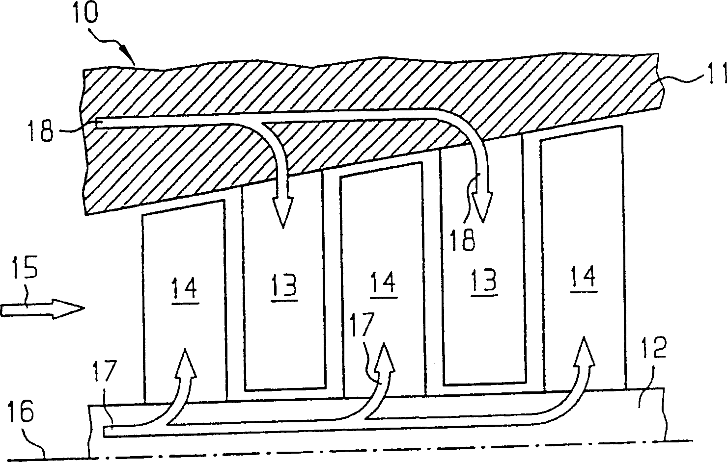
[0029] figure 1 A longitudinal sectional view of a turbine 10 with a housing 11 and a rotor 12 is shown. The housing 11 is provided with guide vanes 13 and the rotor 12 is provided with rotor blades 14 . In operation, fluid flows through the turbine 10 in the direction of arrow 15 , the fluid flows along the guide vanes 13 and rotor blades 14 , causing the rotor 12 to begin rotating about a centerline 16 .

[0030] In most applications, the temperature of the fluid is high, especially in the region of the first row of blades ( figure 1 shown in the center left). For this purpose, a cooling system is provided for the guide blades 13 and the rotor blades 14 . The flow of cooling fluid is schematically indicated by arrows 17 , 18 .

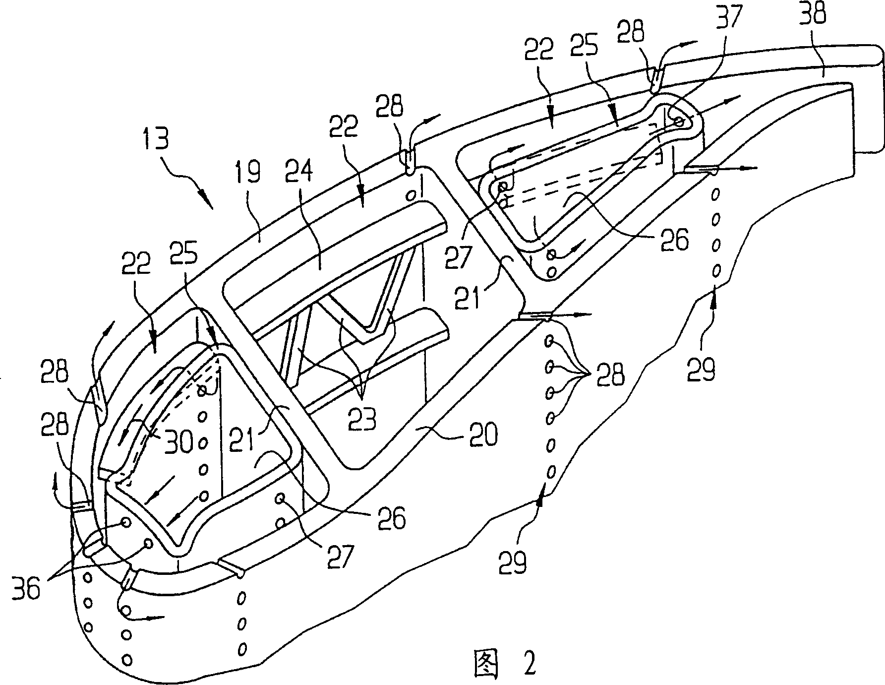
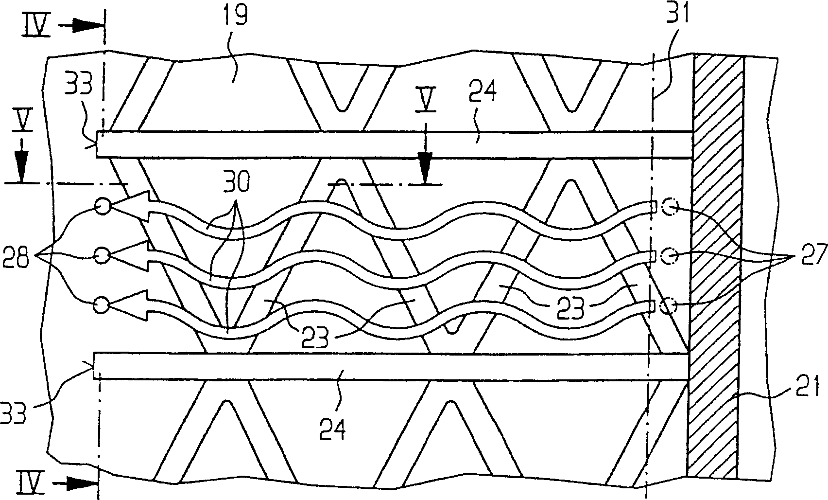
[0031] FIG. 2 schematically shows an exploded view of the guide vane 13 . The guide vanes 13 have curved outer walls 19 , 20 . The interior space between the outer walls 19 , 20 is subdivided into a total of three ducts 22 by means of two parti...


PUM


Abstract

The blade (13) has at least one channel (22) bounded by walls (19-21), whereby an insert (25) exposed to at least one cooling fluid is inserted into at least one channel. At least one wall has horizontal ribs (24) between the insert and the wall and the insert has openings (27) via which the cooling fluid can pass out of the insert between the horizontal ribs.

Description

technical field [0001] The invention relates to a blade, in particular a turbine blade, having at least one duct delimited by walls, into which a cooling fluid is directed onto an insert. Background technique [0002] Such a blade is known from US5419039. A cavity extending in the direction of the longitudinal centerline of the blade is formed between the insert and each wall of the blade. Cooling fluid gushes from the insert into these cavities and impinges on the walls of the blade. The cooling fluid then flows along the walls and pours through the outlets into specially shaped cavities on the outlets of the walls and from there into the surrounding environment. In known blades, as the cooling fluid flows along the walls, the effect of convective cooling is only insignificant due to the extremely limited flow length. Furthermore, the cooling fluid mixes in the chamber along the longitudinal centerline of the blade, so that no targeted cooling can take place. [0003] A...

Claims


Application Information

Patent Timeline
IPC IPC(8): F01D5/18F01D9/02
CPCF01D5/189F05D2260/2212F05D2260/22141F05D2260/201
Inventor 彼得·蒂曼
Owner SIEMENS AG
Learn More