Brushless DC motor for air-conditioner of vehicle
A brushed DC motor, automotive air conditioner technology, applied in electrical components, electromechanical devices, electronic commutators, etc., can solve problems such as sparks, high noise, and interference life.
- Summary
- Abstract
- Description
- Claims
- Application Information
AI Technical Summary
Problems solved by technology
Method used
Image
Examples
Embodiment 1
[0024] Such as figure 1 Shown is a schematic structural diagram of the brushless DC motor body. Among them, 1 is the bearing, 2 is the end cover, 3 is the casing, 4 is the permanent magnet rotor, 5 is the air gap, 6 is the stator, 7 is the winding, 8 is the Hall position sensor assembly, 9 is the sensor lead wire, 10 is the Motor lead-out line, 11 is main shaft.
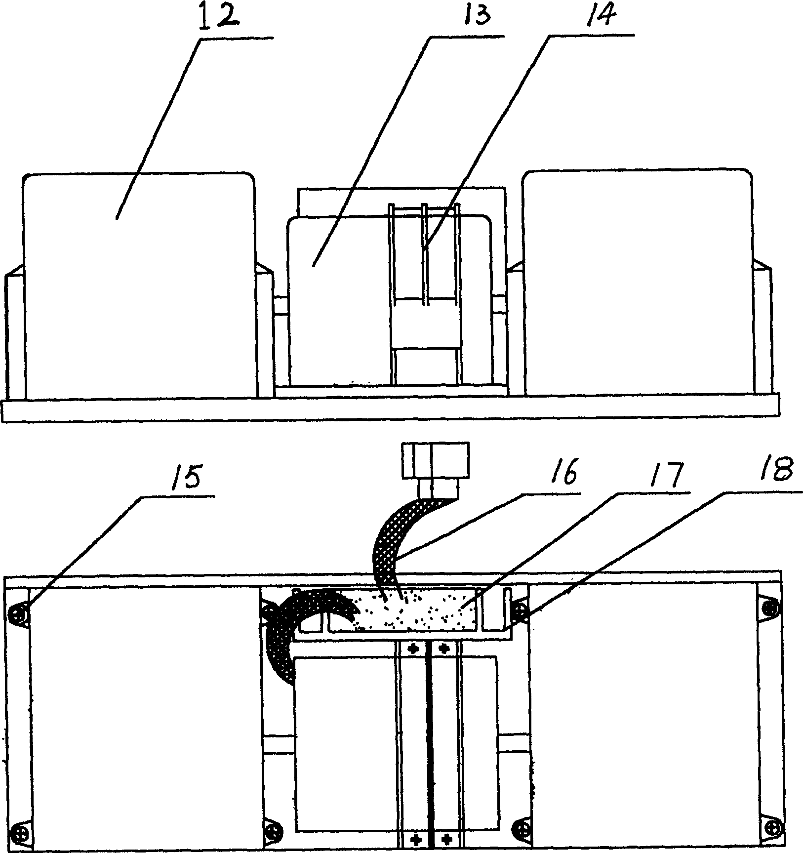
[0025] For the structure of DC27V brushless DC evaporating fan for medium and large vehicles, see image 3 , by the volute 12, motor 13, fixed clip 14, set screw 15, lead plug 16, position sensor, electronic switch circuit 17, radiator 18 and so on.
[0026] As shown in Figure 4, it is a schematic diagram of the structure of a DC27V brushless DC condensing fan. The condensing fan is composed of a fan blade 19, a motor 20, a motor lead wire 21, a sensor, a sensor lead wire 22, an input lead wire 23 connected to the motor lead wire, and a sensor lead wire. Input lead wire 24, electronic switch circuit 25, radiator 2...
Embodiment 2
[0033] The DC27 (or 24V) brushless DC motor suitable for large and medium-sized vehicles of the present invention can be controlled by a half-control circuit in addition to the full-control circuit described in Embodiment 1. The full-control circuit has better performance and higher efficiency; However, the cost of the semi-controlled circuit is slightly lower, and its specific circuit diagram is as follows: Figure 5 Shown:
[0034] Sensor: mainly composed of Hall position sensors H1, H2, H3, resistors R1, R2, R3, capacitors C1, C2, C3, etc. When the motor rotor magnetic field passes through the Hall element, the Hall 3 pin will output a trigger signal , so the position of the rotor magnet relative to the stator can be detected according to the waveform signals output by Hall H1, H2, H3, so as to control the electrification of the stator winding accordingly.
[0035] Electronic switch circuit board: integrated with inverter IC1 (4069 six inverters), four-input NAND gate IC2 ...
PUM
 Abstract
Description
Claims
Application Information
 - R&D
- Intellectual Property
- Life Sciences
- Materials
- Tech Scout
- Unparalleled Data Quality
- Higher Quality Content
- 60% Fewer Hallucinations
Browse by: Latest US Patents, China's latest patents, Technical Efficacy Thesaurus, Application Domain, Technology Topic, Popular Technical Reports.
© 2025 PatSnap. All rights reserved.Legal|Privacy policy|Modern Slavery Act Transparency Statement|Sitemap|About US| Contact US: help@patsnap.com


