
Hydraulic piston having enclosed cavity and method for making the same

A cavity and piston technology, applied in the field of hydraulic pistons and its manufacturing, can solve the problems of expensive manufacturing

Inactive Publication Date: 2006-11-29
SAUER DANFOSS NORDBERG
View PDF1 Cites 2 Cited by
  • Summary
  • Abstract
  • Description
  • Claims
  • Application Information

AI Technical Summary

Problems solved by technology

While a piston of this design solves at least some of the problems mentioned above, it is very expensive to manufacture

Method used


Image

  • Hydraulic piston having enclosed cavity and method for making the same
  • Hydraulic piston having enclosed cavity and method for making the same
  • Hydraulic piston having enclosed cavity and method for making the same

Examples


Embodiment Construction

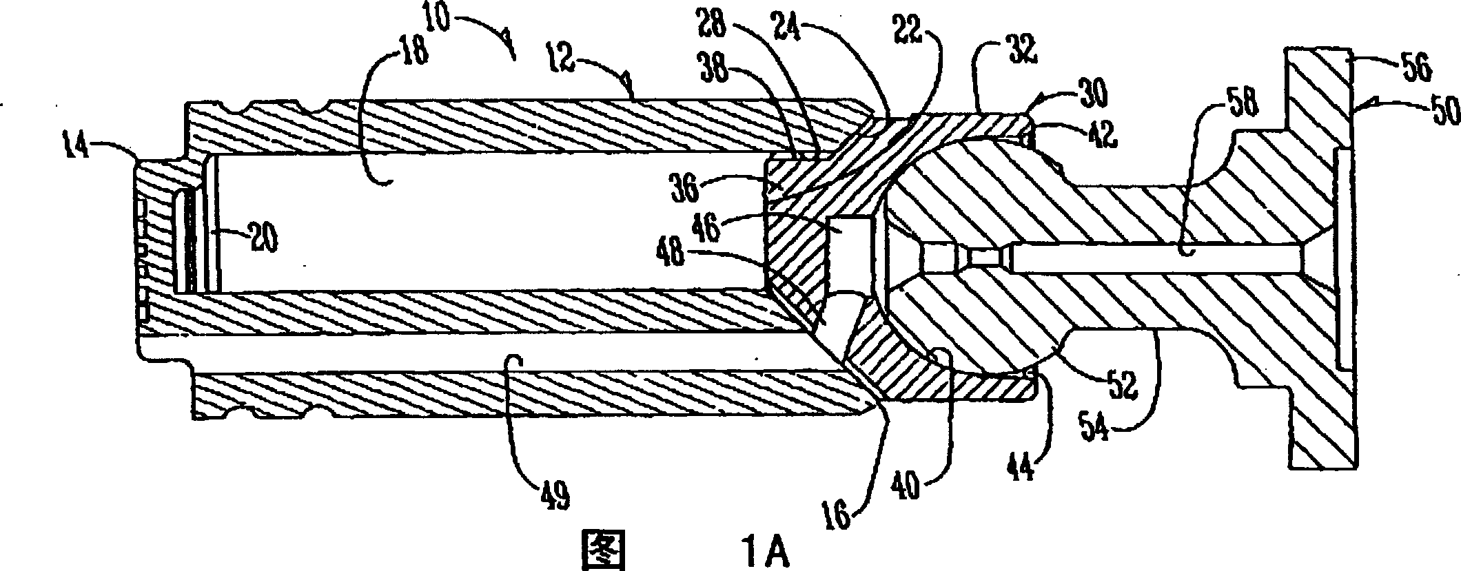
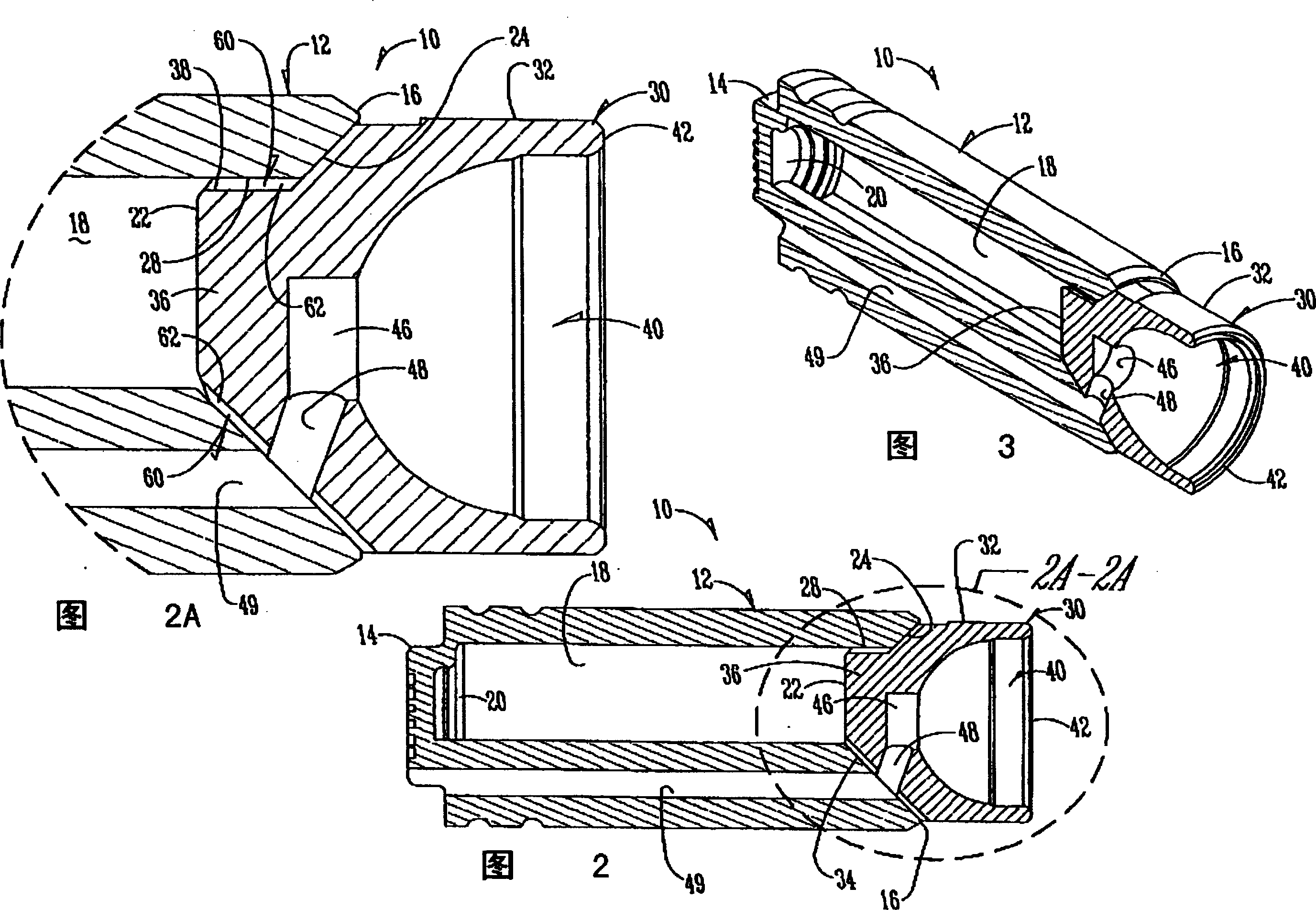
[0035] see figure 1 To 7, numeral 10 designates a hydraulic piston having a cylindrical body 12 with a first end 14 and a second end 16. An elongated cavity 18 is formed in the body 12 and has a first end 20 and a second end 22 . A tapered surface 24 is formed on body 12 at second end 22 surrounding cavity 18 . Referring to FIG. 2A , a cylindrical side wall portion 28 extends inwardly from the inner tapered surface 24 .

[0036] Cap 30 has a cylindrical head 32 and a tapered side wall 34 (FIG. 4). A cylindrical stub 36 extends inwardly into the cavity

[0037] 18 of the second end 22 . Post 36 has a cylindrical side wall 38 which extends into cavity 18 at its second end.

[0038] Cover 30 has a curved ball socket 40 which terminates in an annular lip 42, such as figure 1 As shown in A. A small space 44 will accommodate the curling of the lip 42 in an inward direction, as will be discussed below.

[0039] The cover 30 has a central conduit 46 aligned with an angled cond...


PUM


Abstract

The hydraulic piston used in a cylinder body of a hydraulic power unit has a long cylindrical body inside of which is a cavity. A cap is adhered to the body to close the cavity. The piston has an elongated first conduit formed in the body which is separate from the cavity. The conduit communicates with a second conduit in the cap thereof to permit transmission of oil through the conduit without invading the volume of the cavity. The body member and the cap are of metallic construction with the material of the cap member being more malleable than the material of the body. The cap is adapted to terminate either in a spherical ball for attachment to a slipper element, or is comprised of a spherical socket adapted to receive a ball element attached to a slipper element.

Description

technical field [0001] The present invention relates to hydraulic pistons and methods for their manufacture. Background technique [0002] Certain hydraulic pistons used in the cylinders of hydraulic power units have a solid steel construction. Although they are durable, reliable and inexpensive to manufacture, their relatively large weight limits the speed at which they can be operated. They also generate high running friction. [0003] Additionally, some pistons are formed with hollow cavities in order to reduce the weight of the solid steel piston. However, the hollow cavity is filled with compressible oil. Pressurizing and depressurizing the oil in the piston cavity during the pressure cycle results in ineffective energy consumption and has a detrimental effect on the moment of inertia imparted by the swash plate cooperating with the piston. [0004] The disadvantage of this hollow piston is partly overcome by filling the hollow cavity with plastic, which is relative...

Claims


Application Information

Patent Timeline
IPC IPC(8): B23P15/10F16J1/00B22F3/22F04B1/16B22F3/02B22F5/00B22F7/06F04B1/12F16J1/08
CPCB22F3/225B22F3/22B22F5/008B22F2998/00F04B1/124F16J1/005F16J1/08
Inventor 罗伯特·J·施托佩克马克·A·兰德韦尔杰伊·H·安克尼阿伦·R·舒斯特
Owner SAUER DANFOSS NORDBERG
Learn More