Twin shaft flexible roll-bending machine based on control of feeding force

A technology of feed force and roll bending machine, which is applied in the field of tube forming equipment and pipe fittings, can solve the problems of uneven material in the working part of the elastic wheel, affecting the forming accuracy of the working section, and different axial forces, etc., to improve the international Competitiveness, simple structure, high precision effect

Inactive Publication Date: 2006-10-25
NANJING UNIV OF AERONAUTICS & ASTRONAUTICS
View PDF0 Cites 0 Cited by
  • Summary
  • Abstract
  • Description
  • Claims
  • Application Information

AI Technical Summary

Problems solved by technology

However, in this manufacturing method, since the elastic body of the large elastic wheel is made of polyurethane material, there is unevenness in the manufacturing process, and aging will occur after a period of use, which will cause the working part of the elastic wheel to be damaged. Material inhomogeneity exists in the axial direction
When the feed rate control is adopted, although the compression amount between the two axes is consistent in the axial direction, the axial force of the work is not the same, resulting in the difference in bending curvature in the forming work, and the rejection rate is high. At the same time It also seriously affects the forming accuracy of the working section

Method used


Image

  • Twin shaft flexible roll-bending machine based on control of feeding force
  • Twin shaft flexible roll-bending machine based on control of feeding force
  • Twin shaft flexible roll-bending machine based on control of feeding force

Examples


Embodiment Construction

[0023] The present invention will be further described below in conjunction with the accompanying drawings and embodiments.

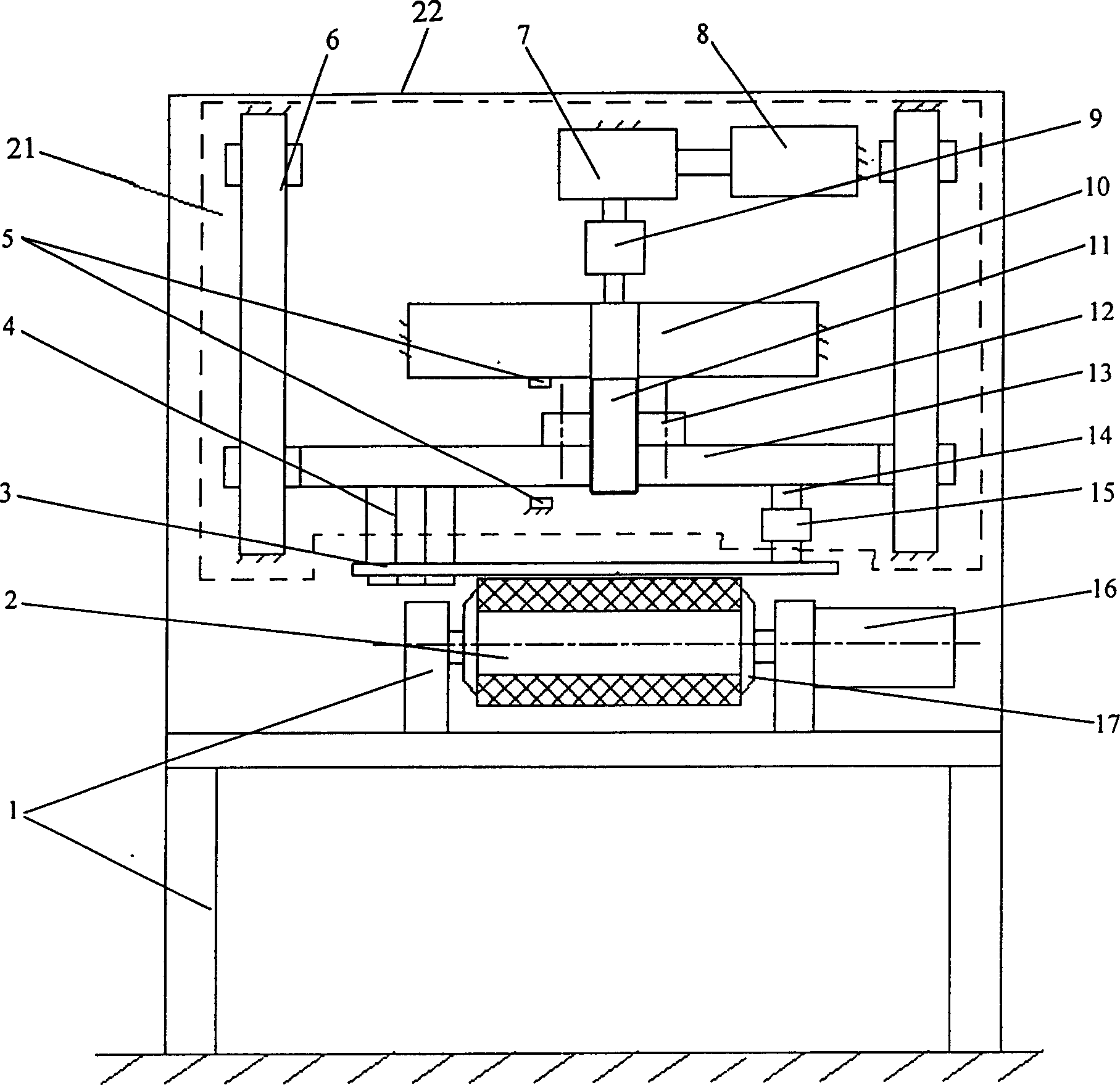
[0024] Such as figure 1 shown.

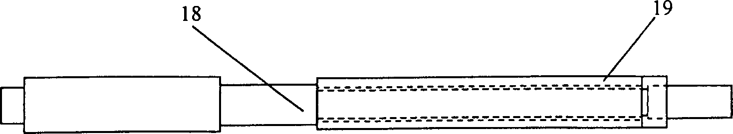
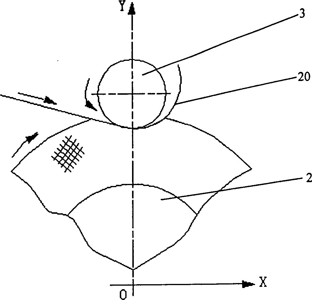
[0025] A two-axis flexible roll bending machine based on feed force control, including a frame 1, a driving roller 2, and a driven roller 3, the driving roller 2 is connected to the frame 1, and the driving wheel 2 is connected to a driving roller driving device 16 The driven roller 3 is connected with the longitudinal driving device 21, the longitudinal driving device 21 and the frame 1 are installed in the casing 22, and the processed workpiece 20 is located between the driving roller 2 and the driven roller 3 and between them Bending and forming under the joint action, the driving roller 2 is composed of a rigid mandrel and an elastic body covered on the rigid mandrel; one end of the driven roller 3 is installed on the support 4 in the longitudinal driving device 21, and the support 4 Connected to one end of the sli...


PUM


Abstract

The invention discloses a method for feeding back the actual extrusion force between a rigid shaft and an elastic wheel to a machine tool control system by using a load cell, and the control system controls the rolling process of a workpiece based on the extrusion force, which can A dual-axis flexible roll bender based on feed force control that realizes the dual functions of precise forming and continuous and discontinuous change of roll curvature, including frame (1), driving roller (2), driven roller (3), driving Roller (2), driven roller (3) are connected with frame (1), driving wheel (2) is connected with driving roller driving device (16), driven roller (3) is connected with longitudinal driving device (21 ) connected, the workpiece to be processed (20) is located between the driving roller (2) and the driven roller (3) and is bent and shaped under their joint action, characterized in that the driving roller (2) consists of a rigid core A shaft and an elastic body coated on a rigid mandrel; a load cell (15) is installed on the connecting piece (14) connecting the driven roller (3) and the longitudinal driving device (21).

Description

technical field [0001] The invention relates to a pipe fitting and barrel molding equipment with a circular cross section and a convex non-circular shape, in particular to a biaxial flexible bending machine based on feed force control. Background technique [0002] As we all know, there are thousands of installation holes on the aircraft, and the processing quality is directly related to the safety of flight. In recent years, in order to improve the fatigue life of the aircraft, aircraft manufacturers have invented a cold extrusion process with slotted bushings to extrude and strengthen these holes. The materials used for slotted bushings are all special stainless steel materials, which are very difficult to manufacture. The traditional rolling technology cannot guarantee its manufacturing accuracy. At present, only a few countries can manufacture this kind of special stainless steel bushings, while my country mainly relies on imports. solve this puzzle. [0003] In additio...

Claims


Application Information

Patent Timeline
Patent Type & Authority Patents(China)
IPC IPC(8): B21D11/20
Inventor 左敦稳王珉闫静黎向锋曹振中徐锋
Owner NANJING UNIV OF AERONAUTICS & ASTRONAUTICS
Why Eureka
Try Eureka