


Quick Research
Generate reliable direction feasibility study reports for your R&D in just a few steps.

Technical Q&A
Discover and master advanced knowledge NOW. Basics, ideas, possibilities, all at once.

Find Solutions
As an expert in R&D theories, this can generate solutions to your technical problems instantly.

Evaluate Feasibility
Analyze your overall solution with one click, know your potential R&D risks in advance.

Monitor Landscape
Get weekly tech updates, stay abreast of the latest tech innovations and key insights.
Compact fluorescent lamp with shell structure
A fluorescent lamp, compact technology, applied in the direction of gas discharge lamps, the use of gas discharge lamps, parts of gas discharge lamps, etc., can solve the problem that fluorescent lamps cannot cover the temperature range, etc.
- Summary
- Abstract
- Description
- Claims
- Application Information
AI Technical Summary
Problems solved by technology
Method used
Image


Examples
Embodiment Construction
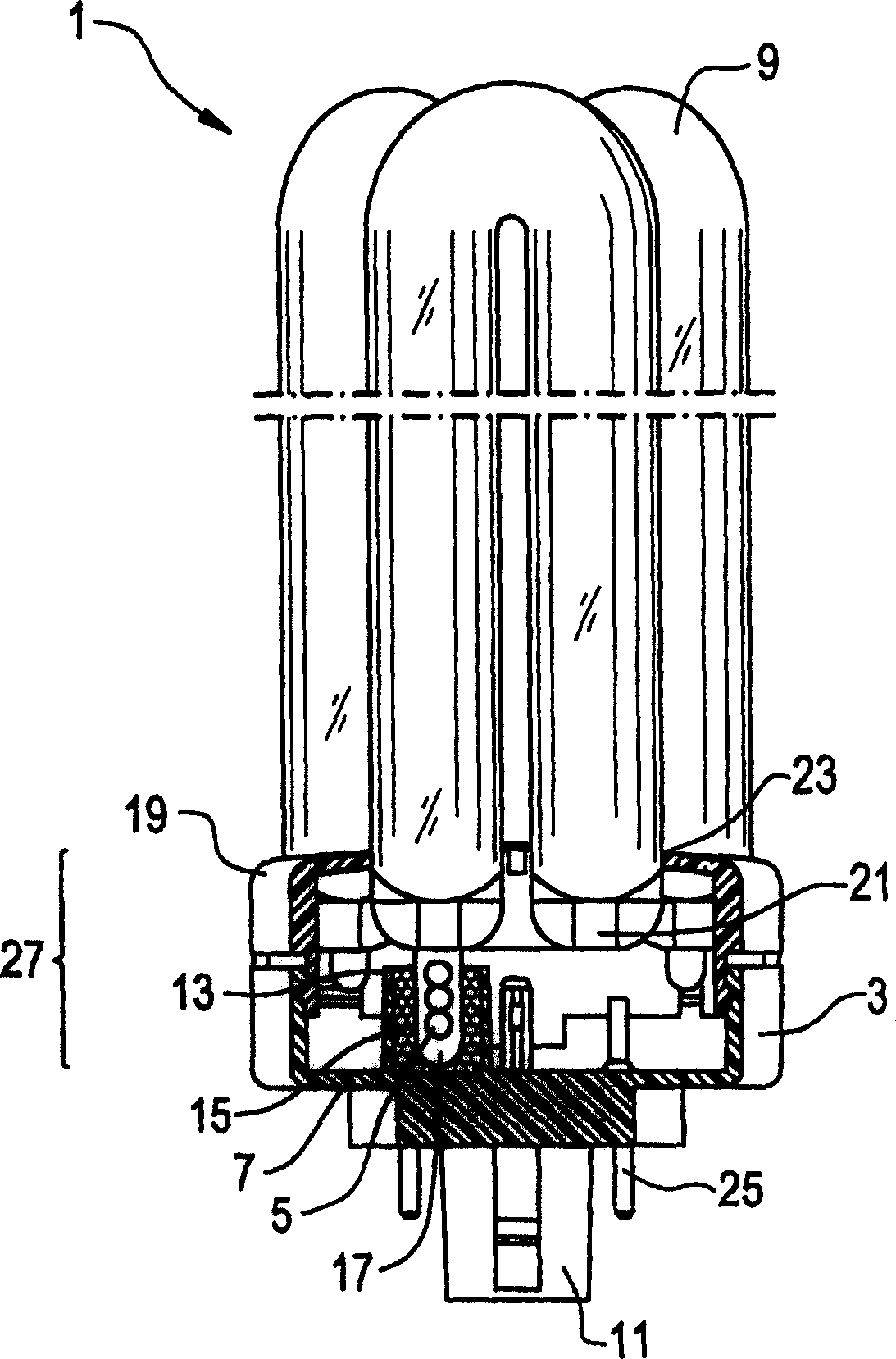
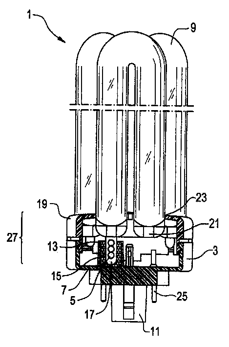
[0011] figure 1 A compact fluorescent lamp 1 with a discharge vessel 9 and a housing 27 is shown. The case 27 includes the case 3 and the cover 19 . The housing 3 and the cover 19 are fixed to each other on their periphery. The discharge vessel 9 comprises three U-shaped tubes whose ends 21 bridge each other so that a continuous path of the discharge arc is formed. The discharge vessel 9 is filled with inert gas and mercury, and the U-shaped tube is sealed at the end 21 . The end 21 of the U-shaped tube extends into the interior of the housing 27 through an opening 23 in the upper part of the cover 19 of the housing 27 and is firmly fixed therein. One end of the U-shaped tube is equipped with a pin 17 communicating with the discharge tube 9 . The amalgam ball 5 is housed in the pin 17 and extends down to the bottom of the housing 3 . The amalgam ball 5 is placed at the lower end of the pin 17.
[0012] A heat conducting member is provided around the pin 17, which is form...
PUM
 Abstract
Description
Claims
Application Information
 - R&D Engineer
- R&D Manager
- IP Professional
- Industry Leading Data Capabilities
- Powerful AI technology
- Patent DNA Extraction
Browse by: Latest US Patents, China's latest patents, Technical Efficacy Thesaurus, Application Domain, Technology Topic, Popular Technical Reports.
© 2024 PatSnap. All rights reserved.Legal|Privacy policy|Modern Slavery Act Transparency Statement|Sitemap|About US| Contact US: help@patsnap.com