Spring spindle

A technology of spindles and compression springs, which is applied in the field of spring spindles, can solve the problems that the weaving products cannot be guaranteed to be uniform in density, the surface is smooth and smooth, the distance between the knitting machine table tops is limited, and the normal work is affected, so as to achieve light weight, improve the working environment, and reduce costs. Effect

Inactive Publication Date: 2006-05-10
张宝香
View PDF3 Cites 0 Cited by
  • Summary
  • Abstract
  • Description
  • Claims
  • Application Information

AI Technical Summary

Problems solved by technology

[0002] Although Chinese Patent No. 99235964.3 "Double Rod Spindle for Rope Braiding Machine" also provides a kind of spindle used on the braiding machine, the double rod spindle of this kind of structure cannot solve the problem that the braided wire is loose inside and outside during the braiding process. Therefore, we cannot guarantee that the density of the woven product is uniform, the surface is smooth and smooth, and there is no loose thread phenomenon, but the noise is large.
[0005] Although the above two patents have made different improvements to the structure of the spring spindle, which have played a certain role and effect in improving product quality, it has been found through long-term use that there are still some defects, such as the spring on the connecting rod is completely exposed, easy to damage, and affects its normal work
[0006] In addition, if the spindle is required to weave multiple threads, the traditional method is to adjust and replace the slider on it so that the weight moving up and down matches the tension of the braiding thread on it, that is, the weight is changed. Larger sliders often have a larger weight and larger volume, and the distance between the table tops of the knitting machine is limited. If the sliders are too large, they will collide with each other and cannot work normally, thus limiting their processing. scope, there are significant limitations

Method used


Image

  • Spring spindle
  • Spring spindle
  • Spring spindle

Examples


Embodiment Construction

[0017] The present invention will be described in further detail below in conjunction with accompanying drawing embodiment:

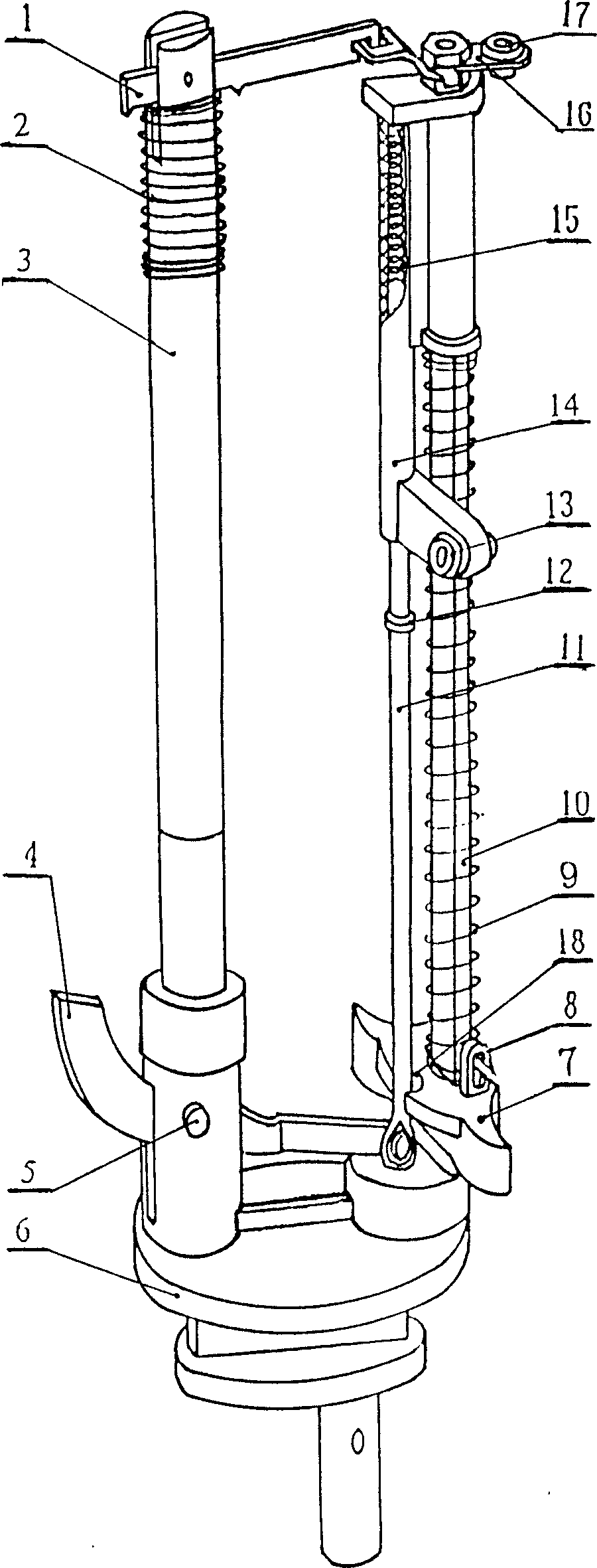
[0018] Left and right columns 3,10 are die-cast in the through hole at the top of the runway bar 6, and are fixed into one body to form a fixture.

[0019] The left column 3 is cylindrical, with an open slot in the middle of the top, and two corresponding through holes communicated with the middle open slot on the front and rear walls.

[0020] Right column 10 sections are waist-shaped, and the top is screw rod.

[0021] The track bar 6 is the same as the prior art, and is injection-molded by composite material, wear-resistant and low-noise.

[0022] Slide block 7 is made by metal material, is the gold ingot shape that waist-shaped through hole is arranged in the middle, has a circular arc-shaped gap 18 at the inner side upper end, the middle edge place, and a screw hole is arranged on the upper surface.

[0023] Wire hook 8 is made by high wear-resis...


PUM


Abstract

A low-noise spring spindle, the main weaving part of the knitting machine, suitable for weaving wires, cables, glass fiber tubes, ropes, automobile and motorcycle assembly lines, liquefied gas hoses, rubber reinforced tubes, etc. The lower end of the right column passes through the slider and is fixed on the runway pole. One end of the switch piece is connected to the lower end of the connecting rod, the other end passes through the lower end of the left column through the hole, and is connected with the left column with a compression spring by a pin. One end of the movable pin is connected to the left column. The column is connected, and the other end is connected with the porcelain frame fixed on the right column. The bracket with the incoming line porcelain eye is connected with the right vertical rod and the connecting rod covered with the spring and fixed with the porcelain frame with the outgoing line porcelain eye. The slider is fixed with a wire hook, and the bracket is made of plastic injection molding. One side is equipped with a spring to cooperate with the connecting rod, and the other side is fixed on the right column. The spring on the right column can be exchanged for multiple wires. Braid, and match slider weight. The scope of use is expanded, and one braiding machine can be used for multi-variety weaving, which reduces the production cost.

Description

technical field [0001] The invention relates to a main braiding part on a braiding machine, especially for braiding wires, cables, glass fiber tubes, ropes, automobile and motorcycle assembly lines, liquefied gas hoses, rubber reinforced tubes, braided tubes, etc. The spring spindle used on the machine. Background technique [0002] Although Chinese Patent No. 99235964.3 "Double Rod Spindle for Rope Braiding Machine" also provides a kind of spindle used on the braiding machine, the double rod spindle of this kind of structure cannot solve the problem that the braided wire is loose inside and outside during the braiding process. Therefore, we cannot guarantee that the weaving products have uniform density, smooth surface, and no loose threads, but the noise is large. [0003] Chinese Patent No. 92222751.9 "Low Noise Spring Spindle" also provides the spindle used on the braiding machine, and by installing an adjustment device on the column, it solves the phenomenon of inner l...

Claims


Application Information

Patent Timeline
Patent Type & Authority Patents(China)
IPC IPC(8): D04C3/40
Inventor 张宝香
Owner 张宝香
Why Eureka
Try Eureka