
Adjustable optical mechanism

An optical mechanism and adjustable technology, which can be used in TVs, color TV parts, electrical components, etc., can solve the problems of impracticality and inability to provide better image quality

Inactive Publication Date: 2006-04-26
AVISION PRECISION IND (SUZHOU) CO LTD
View PDF0 Cites 0 Cited by
  • Summary
  • Abstract
  • Description
  • Claims
  • Application Information

AI Technical Summary

Problems solved by technology

According to the current situation of higher and higher image quality requirements, such an adjustment method is no longer practical and cannot provide better image quality

Method used


Image

  • Adjustable optical mechanism
  • Adjustable optical mechanism
  • Adjustable optical mechanism

Examples


Embodiment Construction

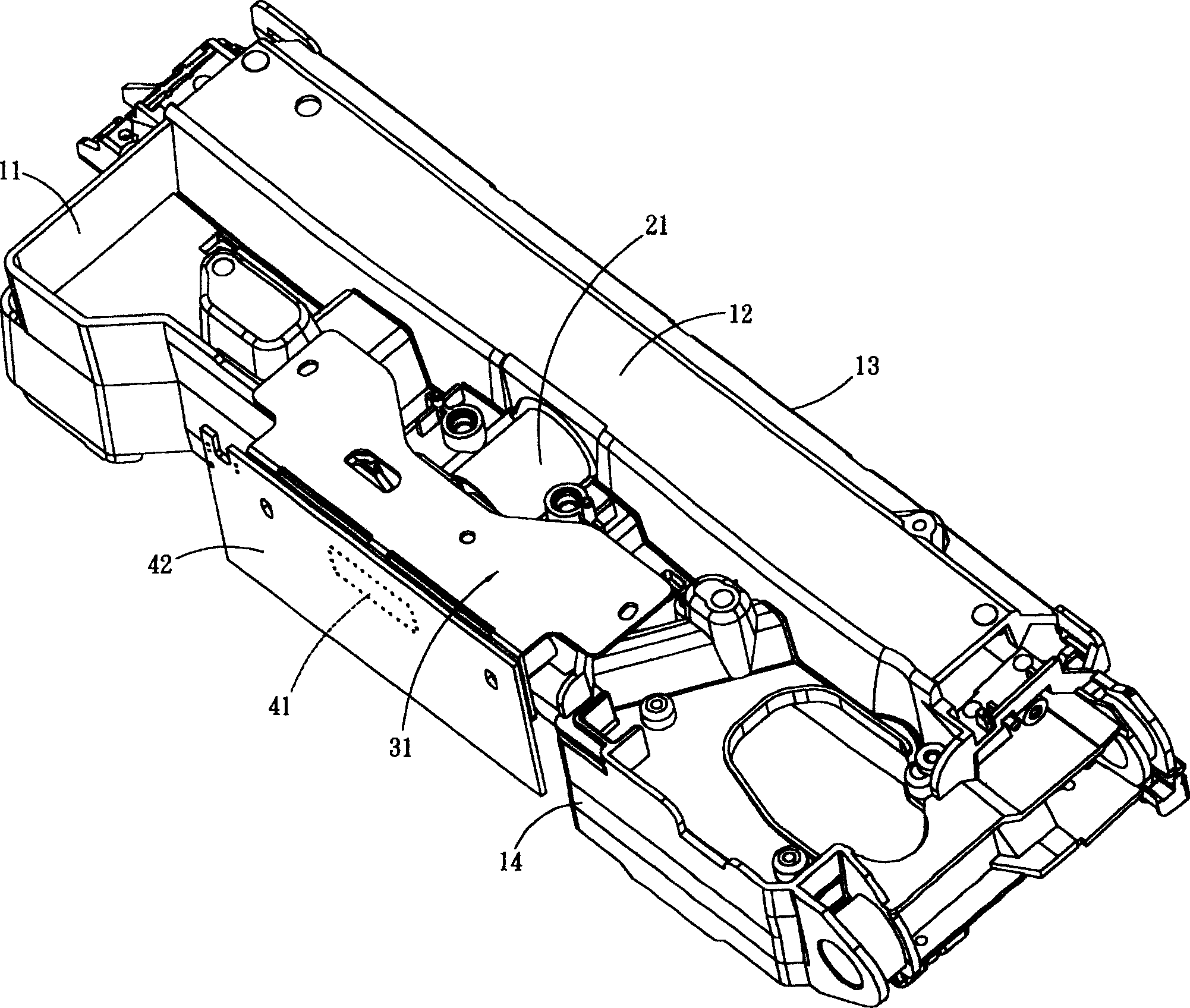
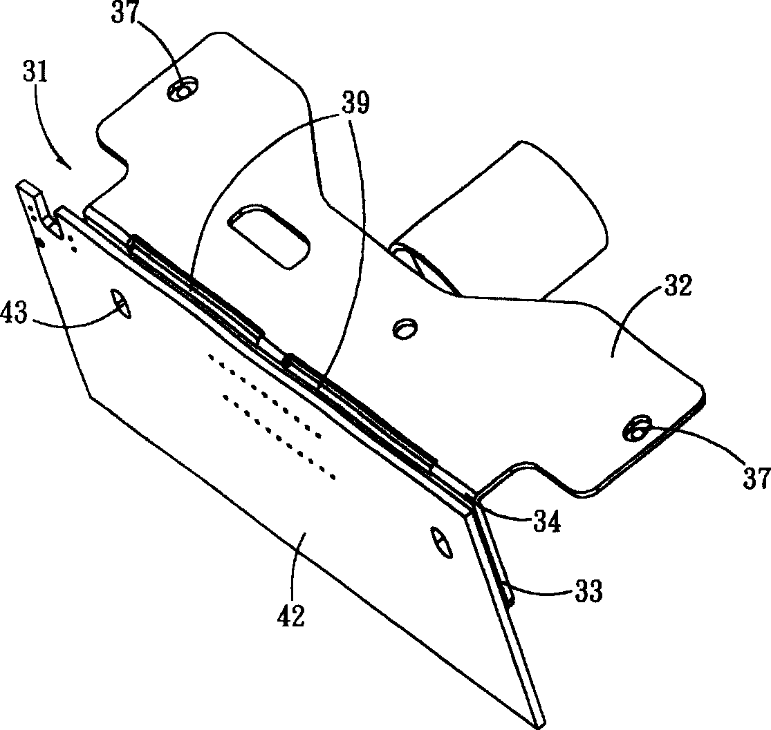
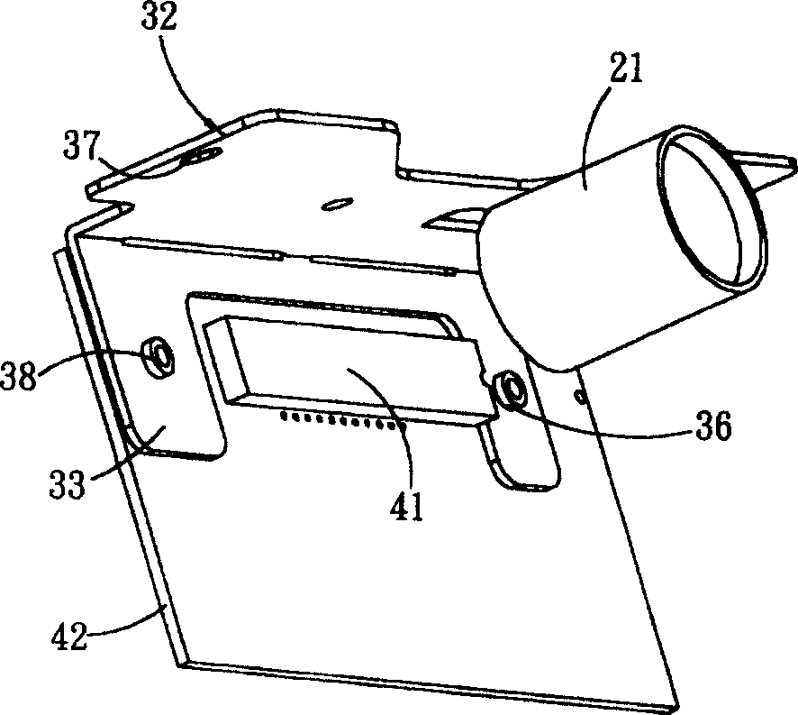
[0016] figure 1 It is a combination diagram of the present invention. The figure discloses an optical machine base 11 , a lens 21 , an adjustment plate 31 , a circuit board 42 , and an image sensing component 41 .

[0017] A mirror assembly 12 is formed on the first side 13 of the optical machine base 11 . The reflector group 12 includes at least one reflector for receiving and reflecting the image information corresponding to the document. The lens group 21 is arranged in the optical machine base 11 and can receive the image information transmitted by the mirror group 12 .

[0018] In another embodiment, the optical base 11 is only assembled with the lens 21 , and does not need to be assembled with any mirror. For example, the lens 21 of the optical machine base 11 can directly receive the image information corresponding to the scanned document, or the optical machine base 11 can be separated from the mirror group, and so on.

[0019] The adjustment plate 31 is assembled ...


PUM


Abstract

An adjustable optical mechanism includes an optical machine base, an adjustment plate assembled on the optical machine base, and a circuit board assembled on the adjustment plate. An image sensing component is assembled on the circuit board, and the image sensing component corresponds to the lens arranged on the optical machine base. In this way, through the deformation of the adjustment plate itself and the adjustment of its position and skew relative to the optical base, the position of the image sensing component can be adjusted to an optimal position to obtain better image quality.

Description

technical field [0001] The invention relates to an optical mechanism, in particular to an adjustable optical mechanism capable of finely adjusting the position and inclination of an image sensing component. Background technique [0002] The optical mechanism in the scanner mainly includes a combination of an optical base, a lens and an image sensing component. A general image sensing component (such as a CCD) is fixed on a circuit board, and the circuit board is fixed on the optical base so that the image sensing component can correspond to the lens. [0003] Since the circuit board is provided with a long hole, when the circuit board is locked on the optical base, the position of the circuit board can be moved, and its inclination can be adjusted, so that the image sensing component and lens appear better corresponding state. The corresponding results of the image sensing components and lenses can be interpreted by auxiliary devices (such as computers...

Claims


Application Information

Patent Timeline
Patent Type & Authority Patents(China)
IPC IPC(8): H04N5/30H04N1/024
Inventor 盛少澜
Owner AVISION PRECISION IND (SUZHOU) CO LTD
Learn More